Star topology guide
Info: 3571 words (14 pages) Study Guides
Published: 15 Apr 2026
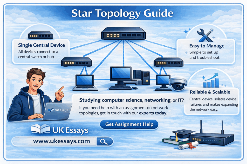
Studying computer science, networking, or IT? If you need help with an assignment on network topologies, get in touch with our experts today. Check out our assignment help page for more information.
Star topology is one of the most widely deployed network configurations in modern computing. From small office networks to large enterprise environments, the star arrangement – where every device connects to a single central node – underpins the vast majority of local area networks (LANs) built today. This guide provides a thorough examination of star topology: its definition, how it works, its advantages and disadvantages, how it compares to other topologies, and its practical significance in real-world networking.
What is star topology?
Star topology is a network configuration in which every node (computer, printer, server, or other networked device) connects individually to a single central device, typically a switch or hub. All data traffic between nodes passes through this central device, which manages the flow of information across the network.
A concise definition:
Star network topology is a LAN architecture in which each node is connected by a dedicated point-to-point link to a central hub or switch. The central device acts as a conduit, receiving data from any sending node and forwarding it to the intended destination node.
The term “star” derives from the physical appearance of the arrangement: when drawn as a diagram, the central device sits at the centre with connections radiating outward to each node, resembling a star.
Star topology can refer to both the physical topology (how cables are actually laid out) and the logical topology (how data flows through the network). In most modern implementations, a network may be physically wired in a star configuration while operating logically as a different topology. For example, early Token Ring networks used a physical star layout (with a multistation access unit at the centre) but passed data logically in a ring. This guide focuses primarily on networks that are both physically and logically configured as stars, which describes the overwhelming majority of contemporary Ethernet LANs (Tanenbaum and Wetherall, 2011).
How star topology works
The operation of a star network follows a straightforward sequence:
- A node generates data. When a device—say, a workstation—needs to communicate with another device on the network, it creates a data frame containing the destination device’s MAC address (at the data link layer) or IP address (at the network layer).
- The data travels to the central device. The frame passes along the dedicated cable connecting the sending node to the central switch (or hub).
- The central device processes the frame.
- If the central device is a hub, it simply replicates the frame and broadcasts it out through every port. Every connected node receives the frame, but only the intended recipient processes it; all others discard it.
- If the central device is a switch (the standard in modern networks), it reads the destination MAC address, consults its MAC address table, and forwards the frame only to the port connected to the intended recipient. This is far more efficient.
- The destination node receives the data. The recipient device processes the incoming frame and, if a response is required, sends a reply back through the central device using the same process.
This centralised communication model means that no node communicates directly with any other node. Every exchange is mediated by the central device. This has profound implications for performance, fault tolerance, security, and management—all of which are explored in the sections that follow.
Physical media
Star networks can be implemented using various physical media:
- Unshielded twisted pair (UTP) cable – The most common medium for wired star networks. Category 5e, Category 6, and Category 6a cables support Ethernet speeds from 1 Gbps to 10 Gbps over distances up to 100 metres per segment.
- Fibre optic cable – Used for higher speeds (10 Gbps, 40 Gbps, 100 Gbps) or longer distances, particularly in backbone connections between switches.
- Wireless – A wireless access point (WAP) acts as the central device in a wireless star topology. Each wireless client associates with the access point, which mediates all communication. The IEEE 802.11 infrastructure mode operates as a logical star (IEEE, 2020).
Star topology diagram
A standard star topology diagram illustrates the following structure:
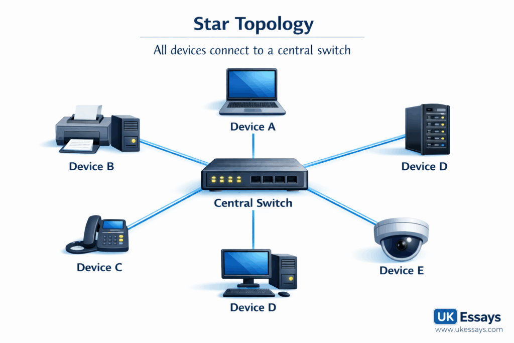
Key features visible in the diagram:
- Central device – The switch (or hub) sits at the centre of the network.
- Point-to-point links – Each node connects to the central device via its own dedicated cable. No cable is shared between nodes.
- No direct inter-node connections – Nodes do not connect to each other. All communication is routed through the centre.
In a more realistic enterprise diagram, the central switch might connect to multiple switches in a hierarchical arrangement (see Extended star topology below), and the nodes might include workstations, printers, servers, IP phones, wireless access points, and other networked devices.
The role of the switch in star topology
The central switch is the single most critical component in a star network. Its role extends well beyond simply passing data from one port to another.
Core functions
| Function | Description |
|---|---|
| Frame forwarding | The switch reads the destination MAC address of each incoming frame and forwards it only to the appropriate port, using its MAC address table (also called a CAM table). |
| MAC address learning | When a frame arrives, the switch records the source MAC address and the port it arrived on. Over time, this builds a complete table mapping every device to a port. |
| Collision domain isolation | Each port on a switch represents a separate collision domain. This eliminates the collisions that plagued shared-medium networks (such as those using hubs or coaxial bus topologies), dramatically improving performance. |
| Full-duplex communication | Modern switches support full-duplex transmission on each port, allowing simultaneous sending and receiving. This effectively doubles the available bandwidth per connection. |
| Loop prevention | Switches running Spanning Tree Protocol (STP) or Rapid Spanning Tree Protocol (RSTP) detect and disable redundant paths that could cause broadcast storms. |
Managed vs unmanaged switches
- Unmanaged switches operate out of the box with no configuration. They are suitable for small networks where simplicity is paramount.
- Managed switches offer configuration options including VLANs (Virtual LANs), Quality of Service (QoS), port mirroring, access control lists (ACLs), and SNMP monitoring. In enterprise star networks, managed switches are essential for segmentation, security, and performance management (Cisco Systems, 2023).
Hubs vs switches: an important distinction
Students frequently conflate hubs and switches. While both can serve as the central device in a star topology, they operate very differently:
| Feature | Hub | Switch |
|---|---|---|
| OSI layer | Layer 1 (Physical) | Layer 2 (Data Link) |
| Frame handling | Broadcasts to all ports | Forwards to specific port |
| Collision domains | Single shared domain | One per port |
| Duplex | Half-duplex only | Full-duplex capable |
| Performance | Degrades as nodes increase | Scales effectively |
| Current usage | Obsolete in most contexts | Industry standard |
Hubs are now largely obsolete. When modern textbooks and industry documentation refer to star topology, they almost universally assume a switch at the centre. However, understanding the distinction remains important for examinations and for appreciating the historical development of networking technology (Kurose and Ross, 2021).
Advantages of star topology
Star topology has become the dominant LAN configuration for compelling reasons. Its advantages span performance, reliability, manageability, and scalability.
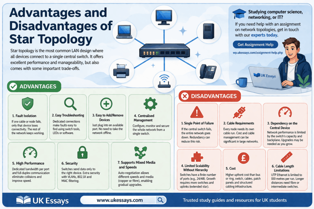
1. Fault isolation
If a single cable or node fails, only that node loses connectivity. The rest of the network continues to operate normally. This is a substantial advantage over bus topology, where a single cable break can disable the entire network, or ring topology, where a single node failure can disrupt the token-passing circuit (unless dual-ring redundancy is implemented).
2. Ease of troubleshooting
Because each node has a dedicated connection to the central switch, faults are straightforward to locate. Network administrators can identify the affected port using switch diagnostic tools, LED indicators, or network management software, and isolate the problem without disrupting other users.
3. Ease of adding or removing devices
Adding a new node requires only a cable run to the central switch and an available port. Removing a node is equally simple. Neither operation requires the network to be taken offline or reconfigured (beyond basic switch port configuration in managed environments). This makes star topology highly adaptable to changing organisational needs.
4. Centralised management
The central switch provides a single point of management for the entire network. Administrators can monitor traffic, configure VLANs, apply security policies, and manage bandwidth allocation from one location. This centralised model simplifies network administration considerably.
5. High performance
Modern switches provide dedicated bandwidth to each port, eliminating the contention that characterised shared-medium networks. A 24-port gigabit switch provides each connected device with a full 1 Gbps connection, rather than requiring all devices to share a single 1 Gbps channel. Combined with full-duplex operation, this delivers excellent performance even under heavy load.
6. Security
The switch’s ability to forward frames only to the intended recipient (rather than broadcasting to all ports) provides a baseline level of data privacy. Managed switches extend this with features such as port-based access control (IEEE 802.1X), MAC address filtering, and VLAN segmentation, which can isolate sensitive traffic from general network traffic.
7. Support for mixed media and speeds
Modern switches commonly support auto-negotiation, allowing ports to operate at different speeds (e.g., 100 Mbps, 1 Gbps, 10 Gbps) and with different media types (copper, fibre). This flexibility allows organisations to upgrade incrementally rather than replacing the entire network at once (Forouzan, 2017).
Disadvantages of star topology
Despite its dominance, star topology has genuine limitations that network designers must consider.
1. Single point of failure
The central switch is the network’s most critical vulnerability. If the switch fails, every connected node loses network access simultaneously. This risk can be mitigated through redundancy—deploying dual switches, stacking configurations, or failover mechanisms—but such measures add cost and complexity.
2. Cable requirements
Each node requires its own dedicated cable run to the central switch. In a large network, this means significantly more cabling than a bus or ring topology would require. In a 200-node office, for example, 200 individual cable runs must be installed, terminated, tested, and documented. The cost of cabling, cable management (trunking, containment, patch panels), and the structured cabling infrastructure can be substantial.
3. Dependency on the central device
The performance and capability of the entire network is constrained by the central switch. If the switch lacks sufficient backplane capacity, port density, or processing power, it becomes a bottleneck. Upgrading the switch (or replacing it with a higher-specification model) may be necessary as the network grows—an additional cost consideration.
4. Limited scalability without hierarchy
A single switch has a finite number of ports. A standard access-layer switch typically offers 24 or 48 ports. Once all ports are occupied, further expansion requires additional switches, which introduces the need for inter-switch links, uplink ports, and—in many cases—a move to an extended or hierarchical star topology. While this is standard practice, it adds architectural complexity.
5. Cost
Compared to a simple bus topology (which requires only a single shared cable), star topology involves higher upfront costs: a dedicated switch, individual cable runs for every node, patch panels, and structured cabling infrastructure. For very small or temporary networks, this overhead may not be justified—though in practice, the reliability and performance benefits almost always outweigh the additional cost.
6. Cable length limitations
Each cable run from node to switch is limited by the physical medium. For UTP Ethernet, the maximum segment length is 100 metres (as specified by IEEE 802.3). Nodes beyond this distance require intermediate switches, fibre optic links, or media converters (Spurgeon and Zimmerman, 2014).
Advantages and disadvantages summary
| Advantages | Disadvantages |
|---|---|
| Excellent fault isolation – one failure does not affect the wider network | Central switch is a single point of failure |
| Easy to troubleshoot and diagnose faults | Requires more cabling than bus or ring topologies |
| Simple to add or remove nodes without disruption | Network performance depends on the central device’s capacity |
| Centralised management and monitoring | Limited port density on a single switch constrains scalability |
| High performance with dedicated bandwidth per port | Higher upfront cost than simpler topologies |
| Good baseline security through unicast forwarding | Cable length restrictions (100m for UTP Ethernet) |
| Supports mixed media types and speeds | Redundancy measures add cost and complexity |
Star topology in computer networks: real-world applications
Star topology is not an abstract textbook concept; it is the physical foundation of most networks encountered in practice.
Office LANs
The typical modern office network is a star topology. Workstations, printers, IP phones, and wireless access points connect to access-layer switches, usually located in comms rooms or IDF (intermediate distribution frame) closets on each floor. These access switches then uplink to distribution or core switches in a hierarchical arrangement.
Home networks
A domestic broadband router acts as the central device in a home star network. Wired devices (desktop PCs, smart TVs, games consoles) connect via Ethernet, while wireless devices (laptops, smartphones, tablets) connect via Wi-Fi—but the logical topology remains a star, with the router at the centre.
Data centres
Data centre networks use star-derived topologies extensively. The leaf-spine architecture, now standard in modern data centres, is essentially a two-tier star: every leaf switch (to which servers connect in a star pattern) connects to every spine switch, creating a highly resilient and low-latency fabric (Clos, 1953; Alizadeh et al., 2014).
Wireless networks
IEEE 802.11 infrastructure mode—the standard configuration for Wi-Fi networks—operates as a star topology. Each wireless client communicates with the access point, not directly with other clients. The access point mediates all traffic, just as a wired switch does in a cabled star network (IEEE, 2020).
Star vs mesh topology
Star and mesh topologies represent fundamentally different design philosophies. Understanding their differences is essential for network design decisions and a frequent topic in examinations.
Mesh topology defined
In a mesh topology, every node connects directly to every other node (in a full mesh) or to several other nodes (in a partial mesh). There is no central device; communication can follow multiple paths between any two nodes.
Detailed comparison
| Feature | Star topology | Mesh topology |
|---|---|---|
| Structure | All nodes connect to a central switch | Nodes interconnect directly with each other |
| Redundancy | Low (single point of failure at the switch) unless additional switches are deployed | High (multiple paths between nodes) |
| Fault tolerance | Single node/cable failure is isolated; switch failure is catastrophic | Highly fault-tolerant; network survives multiple link failures |
| Cabling | n cables for n nodes | 2n(n−1) cables for n nodes (full mesh) |
| Cost | Moderate | High (exponential cabling growth) |
| Scalability | Good with hierarchical extension | Poor for full mesh; manageable for partial mesh |
| Management | Centralised, straightforward | Decentralised, complex |
| Performance | High with modern switches | Excellent (dedicated links, no contention) |
| Typical use | LANs, office networks, home networks | WAN backbone links, critical infrastructure, military networks |
When to choose each
Star topology is the appropriate choice for most LAN environments, where centralised management, cost efficiency, and ease of maintenance are priorities. Mesh topology (usually partial mesh) is preferred for WAN interconnections, backbone links between sites, and environments where maximum resilience is essential—such as financial trading networks, military communications, and internet backbone routing (Peterson and Davie, 2022).
In practice, many enterprise networks combine both: a star topology at the access layer (where end devices connect) and a partial mesh at the core and distribution layers (where switches and routers interconnect for redundancy). This hybrid approach captures the benefits of both topologies.
Mathematical note on scalability
The cabling requirement illustrates why full mesh topology does not scale well for large numbers of nodes. In a star network with n nodes, exactly n cables are required (one per node to the central switch). In a full mesh network, the number of cables is:
C=2n(n−1)
For 10 nodes, a star requires 10 cables; a full mesh requires 45. For 100 nodes, a star requires 100 cables; a full mesh requires 4,950. This exponential growth makes full mesh impractical for anything beyond small, critical networks.
Star topology compared to other topologies
While the star-vs-mesh comparison is the most frequently examined, students should also understand how star topology relates to bus, ring, and tree configurations.
Star vs bus topology
| Feature | Star | Bus |
|---|---|---|
| Cable | Dedicated cable per node | Single shared backbone cable |
| Failure impact | Isolated to the affected node | Backbone break disables entire network |
| Performance | Dedicated bandwidth per port | Shared bandwidth; degrades with load |
| Cost | Higher (more cable, switch required) | Lower (minimal cabling) |
| Current relevance | Industry standard | Largely obsolete for LANs |
Bus topology, based on a single coaxial backbone (as in 10BASE2 and 10BASE5 Ethernet), was common in the 1980s and early 1990s but has been almost entirely replaced by star topology due to its fundamental reliability and performance limitations.
Star vs ring topology
| Feature | Star | Ring |
|---|---|---|
| Data flow | Through central switch | Sequentially around the ring |
| Failure impact | Isolated | Single break can disable network (unless dual ring) |
| Latency | Low (one hop through switch) | Variable (depends on position in ring) |
| Token passing | Not used | Used in Token Ring and FDDI |
| Current relevance | Industry standard | Rare in LANs; surviving in some industrial and telecoms networks |
Star vs tree (hierarchical) topology
Tree topology is essentially an extended star—multiple star networks connected in a hierarchy. This is the de facto architecture of most enterprise networks, as discussed in the following section.
Extended star topology
A single switch with a finite number of ports cannot serve a large network. The solution is the extended star (also called hierarchical star or tree topology), which connects multiple star segments through a structured hierarchy of switches.
The three-tier model
Cisco’s classic three-tier hierarchical network model illustrates the extended star approach:
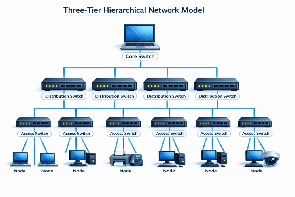
- Access layer – Switches to which end devices connect in a star pattern. Each switch serves a physical area (a floor, a wing, a classroom).
- Distribution layer – Aggregates traffic from multiple access switches, applies routing and policy decisions, and provides redundancy.
- Core layer – High-speed backbone connecting distribution switches across the network. Optimised for fast, reliable forwarding.
This model scales from small offices (where the three tiers may collapse into a single switch) to large campuses with thousands of nodes. Each layer is a star centred on the switches at the tier above, creating a hierarchy of stars (Cisco Systems, 2023).
Two-tier (collapsed core) model
In smaller networks, the core and distribution layers are often merged into a single tier, producing a two-tier architecture:
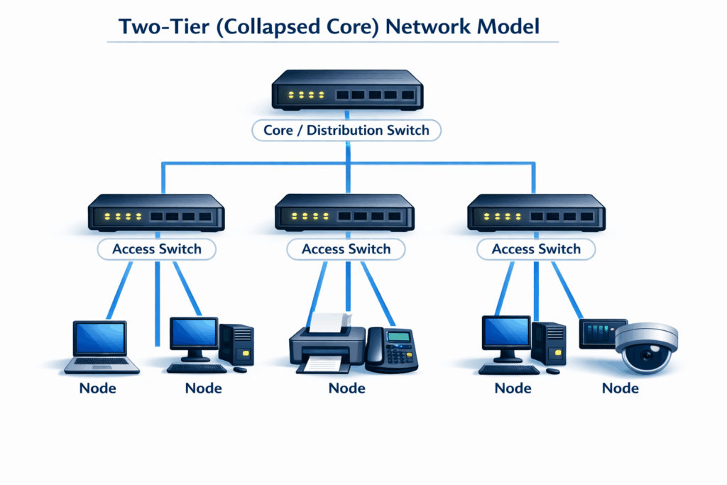
This simplified model reduces cost and complexity while retaining the star topology’s fundamental advantages.
Practical considerations for students and practitioners
For students
- Define your terms precisely. When an examination question asks you to “define star network topology,” provide a clear, concise definition that identifies the central device, the point-to-point links, and the communication model. Avoid vague descriptions.
- Distinguish between physical and logical topology. A network may be physically wired as a star but operate logically as a different topology. Demonstrating this understanding shows depth of knowledge.
- Explain the role of the switch, not just the shape. Many students describe star topology as “devices connected to a central device” without explaining how the switch processes and forwards traffic. Understanding frame forwarding, MAC address learning, and collision domain isolation elevates your answer significantly.
- Use the correct terminology. Refer to “switches” rather than “hubs” when discussing modern networks. If you mention hubs, clarify that they are obsolete and explain the differences.
- Quantify where possible. Using the formula C=2n(n−1) to compare cabling requirements between star and mesh topologies demonstrates analytical rigour.
- Connect to real-world practice. Examiners reward answers that link theoretical topology models to real network implementations. Mentioning Ethernet standards (IEEE 802.3), structured cabling, or the three-tier hierarchical model shows applied understanding.
For practitioners
- Design for redundancy. The single point of failure at the central switch is star topology’s most significant weakness. In production environments, mitigate this with redundant switches, link aggregation (IEEE 802.3ad / 802.1AX), and rapid failover protocols (RSTP, LACP).
- Plan structured cabling carefully. Cable runs in a star topology are numerous and permanent. Invest in proper structured cabling design (following standards such as BS EN 50173 or TIA-568) to avoid costly retrofitting.
- Right-size the switch. Select switches with sufficient port density, backplane bandwidth, and forwarding capacity for current needs and projected growth. An undersized switch will bottleneck the entire network.
- Leverage VLANs. Use VLANs on managed switches to segment the flat star topology into logical subnets, improving security, reducing broadcast traffic, and facilitating policy enforcement.
For extra reading, the most relevant follow-on topics are general network topology comparisons and a dedicated star topology advantages/disadvantages piece. Together, they help readers place star topology in context, compare it with bus, ring, and mesh layouts, and reinforce the main trade-offs around fault isolation, cabling, cost, and the central switch as a single point of failure.
If you prefer to have this and surrounding topics explained this is a useful video:
Studying computer science, networking, or IT? If you need help with an assignment on network topologies, get in touch with our experts today. Check out our assignment help page for more information.
References
- Alizadeh, M. et al. (2014) ‘CONGA: distributed congestion-aware load balancing for datacenters’, Proceedings of the 2014 ACM SIGCOMM Conference. New York: ACM, pp. 503–514.
- Cisco Systems (2023) Campus LAN and wireless LAN design guide. San Jose, CA: Cisco Systems.
- Clos, C. (1953) ‘A study of non-blocking switching networks’, Bell System Technical Journal, 32(2), pp. 406–424.
- Forouzan, B.A. (2017) Data communications and networking. 5th edn. New York: McGraw-Hill Education.
- IEEE (2020) IEEE 802.11-2020 – IEEE Standard for Information Technology – Telecommunications and Information Exchange between Systems – Local and Metropolitan Area Networks – Specific Requirements – Part 11: Wireless LAN Medium Access Control (MAC) and Physical Layer (PHY) Specifications. New York: IEEE.
- Kurose, J.F. and Ross, K.W. (2021) Computer networking: a top-down approach. 8th edn. Harlow: Pearson Education.
- Peterson, L.L. and Davie, B.S. (2022) Computer networks: a systems approach. 6th edn. Cambridge, MA: Morgan Kaufmann.
- Spurgeon, C.E. and Zimmerman, J. (2014) Ethernet: the definitive guide. 2nd edn. Sebastopol, CA: O’Reilly Media.
- Tanenbaum, A.S. and Wetherall, D.J. (2011) Computer networks. 5th edn. Harlow: Pearson Education.
Cite This Work
To export a reference to this article please select a referencing stye below:


