Light-driven Transport of Plasmonic Nanoparticles on Demand
| ✅ Paper Type: Free Essay | ✅ Subject: Engineering |
| ✅ Wordcount: 1348 words | ✅ Published: 30 Aug 2017 |
Abstract
With the advance of science and technology, the control and movement of plasmonic nanoparticles can be achieved via laser traps. The effect of the optical manipulation tool has been tested before on the multiple particles [1]. Here, this is proved that manipulation and transport of large plasmonic nanoparticles can be applied on the sample which previously prepared. These verities include developments related to many technological applications.
Introduction
Metal plasmonic nanoparticles are highly preferred because they have specific properties. These are gold and silver nanoparticles. As we know when the light hits the surface of the metal, a part of the light is reflected. Some of it is absorbed. Metal atoms have electron clouds that are constantly moving around them. The light which is absorbed by metal has energy. That energy causes the vibration of the electron clouds. The vibrations of the electron clouds are called “plasmon” [2]. If we look at the reflected light while we change an angle of incidence we see that reflected light intensity reduces. Resonance angle or SPR angle is the angle at which the maximum loss occurs on the intensity of the reflected light. Localized surface plasmon resonance (LSPR) is the total excitation at the closed surface of a small particle (see Figure 1). These datas are about plasmonics. Plasmonics is an area that consists use of data transmission via plasmons and applications of its various fields.
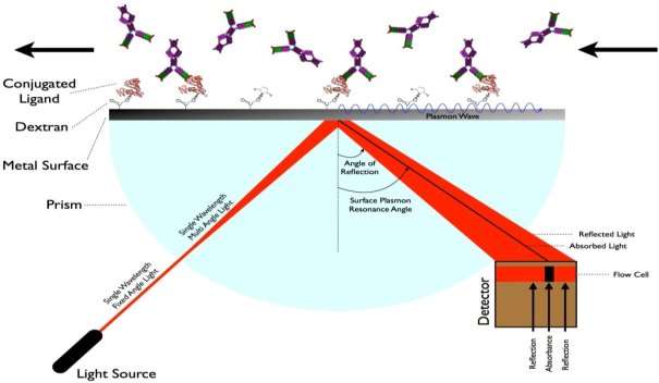
Figure 1: Localized Surface Plasmon Resonance (LSPR)
Laser trap is a method which uses configurable lasers to hold atoms or particles and trap them in a restricted area. There are several different species of laser traps that can be used to trap a different kind of particles. One of the most common types of laser trap is the single-beam gradient force trap also known as optical tweezers or laser tweezers [3].
Dielectric objects are interested in the center of the beam, relatively above the beam waist, shown in the figure (see Figure 2). The force applied on the object depends linearly on its change of location from the trap center just as with a simple arc system [4].
In contrast to other laser traps, the proposed confinement mechanism exploits transverse phase gradient forces that allows working with resonant and off-resonant wavelengths on both red/blue-detuned sides of the LSPR.
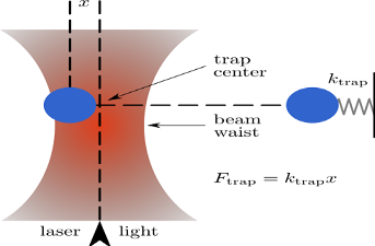
Figure 2: Optical trap principle
The figure below (see Figure 3) shows us spectral absorption on gold and silver nanoparticles. The trapped laser is focused on the sample. Specifically, it is considered colloidal silver NPs of 150 nm (10 nm thick triangular plate, LSPR at 950 nm) and gold NPs of 100 nm (sphere, LSPR at 570 nm). The laser wavelength is arranged 532 nm, which is on the blue-detuned side near the LSPR of gold NPs. In contrast, this wavelength being far from the LSPR of the silver NPs allows avoiding significant optical heating,
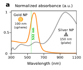
Figure 3: Spectral absorbance of silver and gold nanoparticles
Dark field illumination was applied to create an image of the nanoparticles. With the same microscope objective, focuses on the capture beam on the top glass slides, allowing NPs to be displayed depending on the scattered light (see Figure 4).
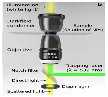
Figure 4: Spectral absorbance
Dark field illumination (or Dark field microscopy) is a method which creates the contrast between the object and the field around the specimen. In this method, the samples and the other materials shine on the dark background (see Figure 5).
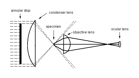
Figure 5: Principle of dark field microscopy
Optical microscopes use dark field illumination technique for enhancing the contrast in unstained samples. The light penetrates the microscopes for illumination of the specimen. The condenser lens and objective lens focuses the light against the specimen. The center is blocked out. The specimen appears bright on a dark background.
The nanoparticles are bounded by the upper glass lamella surrounding the sample (by transverse phase gradient forces, white arrows, and see Figure 6).
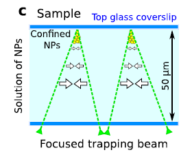
Figure 6: The NPs are confined near the top glass coverslip
Methods
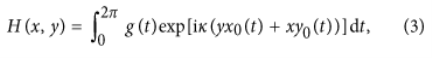
A dipolar NP with size a below the laser wavelength (a < λ) experiences time averaged radiation-induced forces:
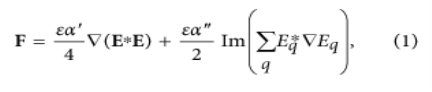
Where, q = x, y, z is a placeholder for the coordinates, α(λ) = α′ (λ) + iα′ ′ (λ) is the particle polarizability while ε is the permittivity of the surrounding medium, and E is the electric field of the focused laser beam.
The particle experiences traverse scattering forces:
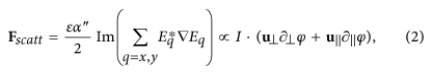
Where, I = |E(x, y)|2 and Ï• are the intensity and phase distributions of the field with u⊥, being normal and tangent vectors to the curve. Therefore, the transverse scattering forces in the normal and tangential directions naturally arise from the phase gradients along such directions.
The laser traps have been created by focusing the following beam over the sample. This is the formula of beam shaping technique:
The sample was formed as like this: the specimen was enclosed into a chamber made by attaching two glass coverslip (thickness 0.17 mm). A Scotch tape (thickness ~50 μm) was used as spacer between the coverslips. The nanoparticles were filled into the sample cell directly from the aqueous solution provided by the manufacturer: 150 nm silver NPs (NanoComposix Inc., 10 nm thick triangular plates, PVP coated, Lott. JMW1340) and 100 nm gold NPs (Sigma-Aldrich, citrate stabilized Au spheres, 742031, Lott. MKBS6913V).
Results
Bottom panel shows the intensity and phase of the laser trap focused according to their shapes (see Figure 7):
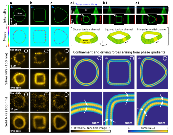
Figure 7:
- It shows us the density and the phase of the laser trap (plane z1) focused into a circle.
- It shows us the density and the phase of the laser trap focused into a square.
- It shows us the density and the phase of the laser trap focused into a triangle.
For each case, the XZ plane profile is shown in a1, b1 and c1 accordingly. In order to display the shape of the toroidal channel displayed in each case of a zoom item (inset) a1, b1 and c1 of the density distribution in plane z2. In the lower panel (a-c) a rotating flow of bound NPs is shown in the toroidal channel for each trap shape. Time skipped images of the stream were also shown[5].
Six small clusters of nanoparticles attached to the coverslip have been used to mimic targets or obstacles as displayed in Figure 8:
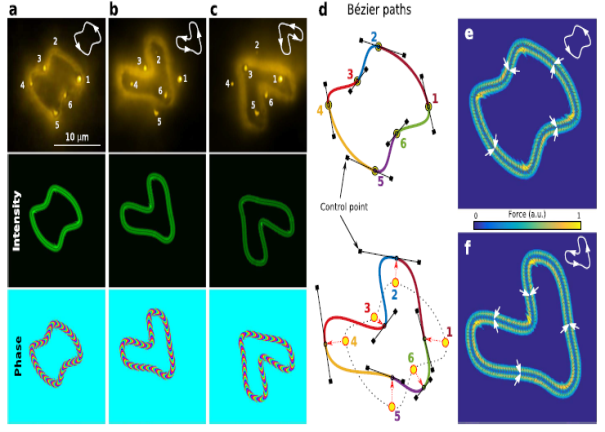
Figure 8
(a) Small clusters of gold nanoparticles which anchored glass microscope slide are carried along a curved Bézier path through six target objects. The intensity and phase of the trapped light (charge l = -30) is configured to avoid these objects as shown in the bottom panel of (b, c). In part (d), proposed approach to automated route finding based on several Bézier curves displayed with different colors. (e,f) distributions of reciprocal and propulsive forces acting on particles[6-9].
Discussion
In this article, gold and silver nanoparticles were controlled and transferred in a prepared sample before thanks to optical manipulation technique. This allows for guiding metal nanoparticles along tailored trajectories for interaction with objects, exploiting off-resonant but also resonant laser wavelengths for simultaneous nanoparticle heating. Their optical response can be tuned in the visible and infrared spectral range as a function of the nanoparticle shape and size. These nanoparticles strongly absorb and scatter light in the spectral region near to their localized surface plasmon resonance (LSPR), and therefore, can be applied as heat nanosources for lithography, photoacustic imaging, photothermal therapy, etc. In this experiment the laser wavelength was 532 nm[5].
References
1.Rodrigo, J.A. and T. Alieva, Freestyle 3D laser traps: tools for studying light-driven particle dynamics and beyond. Optica, 2015. 2(9): p. 812-815.
2.Esentürk, E.N. and A.H. Walker, Anisotropik Åžekilli Altın Nanoparçacıklarının Sentezi, Karakterizasyonu ve Fonksiyonlandırılması.
3.https://people.smp.uq.edu.au/TimoNieminen/trapping.html
4.https://en.wikipedia.org/wiki/Optical_tweezers
5.Alieva, j.A.R.a.T., Light-driven transport of plasmonic nanoparticles on demand. scientific reports, 2016.
6.Carey, K.B., et al., Enhancing Readiness-to-Change Substance Abuse in Persons with Schizophrenia A Four-Session Motivation-Based Intervention. Behavior Modification, 2001. 25(3): p. 331-384.
7.Sanchot, A., et al., Plasmonic nanoparticle networks for light and heat concentration. ACS nano, 2012. 6(4): p. 3434-3440.
8.Lal, S., S. Link, and N.J. Halas, Nano-optics from sensing to waveguiding. Nature photonics, 2007. 1(11): p. 641-648.
9.Svoboda, K. and S.M. Block, Optical trapping of metallic Rayleigh particles. Optics letters, 1994. 19(13): p. 930-932.
Cite This Work
To export a reference to this article please select a referencing stye below:
Related Services
View all


DMCA / Removal Request
If you are the original writer of this essay and no longer wish to have your work published on UKEssays.com then please click the following link to email our support team:
Request essay removal