Effect of Magnetic Field on Hydrodynamic Behavior
| ✅ Paper Type: Free Essay | ✅ Subject: Engineering |
| ✅ Wordcount: 2227 words | ✅ Published: 31 Aug 2017 |
Effect of Magnetic Field on hydrodynamic behavior in a Microchannel Heat Sink
Mohammad Nasiri 1*, Mohammad Mehdi Rashidi 2,
1 Department Mechanical Engineering, Faculty of Mechanical Engineering, University of Tabriz, Tabriz 5166616471, Iran
2 Department of Civil Engineering, School of Engineering, University of Birmingham, Birmingham, UK.
ABSTRACT
In this study, hydrodynamic behavior nanofluid (Fe3O4-water) in a MicroChannel Heat Sink (MCHS) with Offset Fan Shaped under magnetic field was numerically investigated. The two phase mixture model was used to simulate the nanofluid flow. Flow was assumed laminar, steady and incompressible. The effects of changing Reynolds number, power magnetic field, and nanoparticle diameter on fluid behavior are considered. The results show that the friction factor decreases and Nusselt number enhances whit rising Reynolds number. Whit increases intensity magnetic field the pressure drop, friction factor and Nusselt number increasing. The results indicate that non-uniform magnetic field has more effect on nanofluid behavior compare uniform magnetic field.
Keywords
Nanofluid; Microchannel heat sink; Magnetic field; Friction factor; Nusselt number
|
Nomenclature |
|
|
|
Cartesian coordinate axes |
|
|
Velocity component in x and y and z direction, respectively (m/s) |
|
(a,b) |
Center of magnetic wire (m) |
|
|
Velocity vector (m/s) |
|
|
Velocity inlet (m/s) |
|
|
Acceleration vector (m/s2) |
|
|
Thermal conductivity (W/m K) |
|
|
Specific heat capacity at constant pressure |
|
|
Boltzmann constant (1.3806503Ã-10-23 J/K) |
|
|
Temperature (K) |
|
I |
Electric intensity (A) |
|
H |
Magnetic field intensity vector (A/m) |
|
|
Heat flux (1 MW/m2) |
|
|
Channel width (300Ã-10-6m) |
|
|
Hydraulic diameter (0.00001333 m) |
|
|
Channel length (2.70Ã-10-3m) |
|
|
Drag coefficient |
|
|
Mean velocity (m/s) |
|
|
Drift velocity (m/s) |
|
|
Slip velocity (m/s) |
|
d |
Mean diameter (nm) |
|
Nu= |
Nuselt number |
|
|
friction factor |
|
|
Reynolds number |
|
|
Prandtlnumber |
|
|
Magnetic field (T) |
|
Greek symbols |
|
|
|
magnetic permeability in vacuum (4Ï€Ã-10-7 Tm/A) |
|
|
Dynamic viscosity (kg/m s) |
|
|
Thermal expansion coefficient(thermal expansion coefficient (K-1) |
|
|
Density (kg/m3) |
|
|
Mean free path (17Ã-10-9 m) |
|
|
Magnetic susceptibility |
|
|
Particle volume fraction |
|
|
Electrical conductivity (s/m) |
|
Subscripts |
|
|
|
Particle |
|
|
Base fluid |
|
bw |
Bottom wall |
|
|
Effective |
|
|
Average |
 ,z
,z


 =
=


Introduction
Nanofluids has higher thermal conductivities compared to them base fluids [1-5]. Currently the use of nanofluids in thermal engineering systems such as heat exchangers [6-7], microchannels [8-10] , chillers, medical applications [11,12], and solar collectors [13].
Tsai and Chein[14] investigated analytically nanofluid (water-copper and nanotube) flow in microchannel heat sink. They was found that optimum values of aspect ratio and nanofluid did not make conversion in MCHS thermal resistance. Kalteh et al. [15] investigated the laminar nanofluid flow in rectangular microchannel heat sink both numerically and experimentally. Compared the experimental and numerical results presented that two-phase Eulerian-Eulerian method results are in better accordance with experimental results than the single-phase modeling. The reasons experimentally study by Azizi et al.[16] reported that Nusselt numbers decreases whit rising Reynolds number and enhancement heat transfer by using nanoparticles camper to that of pure water for similar Reynolds number. Sheikholeslami et al. [17] studied effect nanoparticle on heat transfer in a cavity square containing a rectangular heated body numerically. They indicated that using nanoparticle increasing heat transfer and dimensionless entropy generation.
Micro channel heat sink (MCHS) using in many applications, such as microelectronics and high energy laser. MCHS cooling is very important because heat flux in this channel higher than regular channel. Many studies analyzed the convective heat transfer characteristics of nanofluids in micro channel heat sink in recently many years ago[18-24].
Sakanova et al. [25] investigated effects of wavy channel structure on hydrodynamic behavior in microchannel heat sink. They found that increasing nanoparticles in pure water the effect of wavy wall unnoticeable. Radwan et al. [26] using nanofluid on heat transfer microchannel heat sink in low concentrated photovoltaic systems investigated numerically. They show that nanofluids is effective technique for enhance heat transfer. Tabrizi and Seyf [27] investigated laminar Al2O3-water nanofluid flow in a microchannel heat sink. They showed that increasing volume fraction of Al2O3 and nanoparticle size reducing the entropy generation.
Chai et al. [28-30] studied hydrothermal characteristics of laminar flow microchannel heat sink with fan-shaped ribs. Their results presented that used the fan-shaped ribs the average friction factor 1.1-8.28 times larger than the regular microchannel, while used the offset fan-shaped ribs was 1.22-6.27 times increases. Also the microchannel with large rib’s height and small rib’s spacing, the frictional entropy generation rate increases and thermal entropy generation rate decreases comparing than the smooth microchannel.
Magnetic fluid (ferrofluid) is a stable colloidal suspension consisting of a base liquid and magnetic nanoparticles that are coated with a surfactant layer and it can be controlled by external magnetic fields [31]. Sundar et al. [32-33] experimentally studied the heat transfer characteristic of Fe3O4 ferrofluid in a circular tube whit applied magnetic field. They detected that the heat transfer increases compared to water flow at same operating condition. Aminfar et al. [34-36] studied effect different magnetic field on ferrofluid for different channels. They showed that using the uniform and non-uniform transverse magnetic increasing heat transfer coefficient and friction factor. Also shown that non-uniform transverse magnetic enhanced heat transfer more than axial non-uniform magnetic field.
In this study, the uniform and non-uniform transverse magnetic effect on heat transfer of ferrofluids flow in a microchannel heat sink with offset fan shaped by using mixture model. The effects of uniform and non-uniform transverse power magnetic fields, Reynolds number and nanoparticle diameter variation are studied in details.
Governing Equations
Researchers presented different models for numerical analysis in multi-phase flows [37-40]. The mixture model is one of methods for nanofluid analyses [38-41]. In this study, flow is assumed steady state, incompressible and laminar with constant thermo-physical properties. The effects of body forces and dissipation are negligible. Also, for calculate the density variations due to buoyancy force was used the Boussinesq approximation. Considering these assumptions, the dimensional equations define as:
Continuity equations:
|
|
(1) |

Momentum equations:
|
|
(2) |

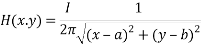
The term  refers to Kelvin force; it results from the electric current flowing through the wire. In this equation, H is Magnetic field intensity vector that determined as [42]:
|
|
(3) |
where
|
|
(4) |
|
|
(5) |
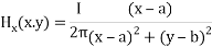
I is electric intensity. The wire direction is parallel to the longitudinal channel and in the center of cross section at the (a, b).
Also, M is the magnetization in Equation (2) and determined as [36]:
|
|
(6) |

where  is magnetic susceptibility of ferrofluid at 4% volume fraction for different mean diameter is present in Table 1.
Table 1. magnetic susceptibility of ferrofluid for different mean diameter
|
mean diameter |
magnetic susceptibility |
|
10 |
0.34858668 |
|
20 |
2.7886935 |
|
30 |
9.4118388 |
In Equation (2),  is called Lorentz force that determined as:
|
|
(7) |

Where  and
and  are respectively effective electrical conductivity and nanofluid velocity vector, also
  is the induced uniform magnetic field that can be calculated by intensity of magnetic field:
|
|
(8) |

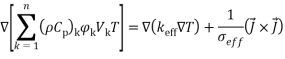
Energy equation:
|
|
(9) |
Volume fraction equations:
|
|
(10) |
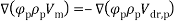
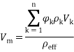
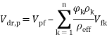
In Equation (10), Vm, and Vdr are the mean velocity and the drift velocity, respectively, that be defined as:
|
|
(11) |
|
|
(12) |

where φ is the volume fraction of nanoparticles.
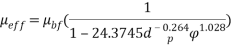
The drift velocity depends on the slip velocity. The slip velocity defined as the velocity of base fluid (bf) with respect to velocity of nanoparticles (p) and determined as:
|
|
(13) |
|
|
(14) |

The slip velocity is presented by Manninen et al. [31e]:
|
|
(15) |
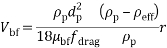
In Equation (15) f drag and r are drag coefficient and acceleration respectively, which can be calculated by:
|
|
(16) |
|
|
(17) |
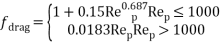
In Equation (16), Rep = Vmdp/veff is the Reynolds number of particles.
Nanofluids Properties
The physical properties of water and Fe3O4 nano-particles are shown in Table 2. The water-Fe3O4 nanofluidis assumed is homogenous that the thermos-physical mixture properties calculated for 4% volume fraction of nanoparticles.
Table 2. Properties of base fluid and nanoparticles [35,40].
|
Properties |
Water |
Fe3O4 |
|
Density (kg/m3) |
997.1 |
5200 |
|
Specific heat capacity (J/kg∙K) |
4180 |
670 |
|
Thermal conductivity (W/m∙K) |
0.613 |
6 |
|
Electrical conductivity (s/m) |
5.3 |
25,000 |
|
Dynamic viscosity (kg/m∙s) |
0.0009963 |
– |
The physical mixture properties are calculated by means of the following equations:
Density of nanofluid:
|
|
(18) |
Specific heat capacity of the nanofluid:
|
|
(19) |

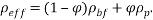
Dynamic viscosity of nanofluid [43]:
|
|
(20) |
Thermal expansion coefficient of nanofluid [35]:
|
|
(21) |
Electrical conductivity [36]:
|
|
(22) |
 .
.Based on the Brownian motion velocity is Thermal conductivity of nanofluid [44]:
|
|
(23) |
dp and dbf are particle diameter(nm) and molecular base fluid (0.2 nm).
In Equation (23) Pr and Re are Prandtl and Reynolds number, respectively defined as:
|
|
(24) |
|
|
(25) |


Also, in Equation (25)  is water mean free path (17 nm) and kB is Boltzmann constant (1.3807 Ã- 10−23 J/K).
Deï¬nition of Physical Domain and numerical method
Fig.1 shown the geometry of the microchannel heat sink with offset fan-shaped reentrant cavities in sidewall. The channel width and space between a pair cavity is 300 μm.The channel length is 2.70 mm with a thickness of 350 μm and the pitch distance of two longitudinal microchannels is 150 μm.
The channel cross section heat sink has a constant width of 100 μm and constant depth of 200 μm and radius of the fan-shaped reentrant cavity is 100 μm.
|
|
|
|
|
|
a) |
b) |
|
|
|
c) |
|
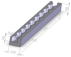
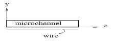
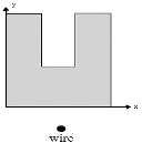
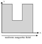
Fig. 1. a) Geometry of microchannel in the present study b) Cross-sectional plane of transverse non-uniform magnetic field c) Transverse uniform magnetic field
In this study, used the finite volume (FV) method to numerically solved non-linear partial differential equations. The velocity pressure coupling by SIMPLEC algorithm. The discretization of momentum and energy equations used the second order upwind scheme and the solid phase equations became discretization by first order scheme.
In this study for evaluate of effect the mesh points on the precision of the results, several grid sizes have been tested for the constant heat flux at Re = 300 are given in Table 3. The 1188000 grids is adequately suitable.
Table 3. Grid independent test (Re = 200,T0 = 300, 4% vol.).
|
V/V0 |
T/T0 |
Grid |
|
1.038 |
1.027 |
672914 |
|
1.029 |
1.019 |
889440 |
|
1.023 |
1.013 |
1188000 |
|
1.02 |
1.011 |
1591128 |
In order to validate this, the amount of mean temperature at the bottom of the microchannel compared by numerical result of Chai et al.[45](Fig.2). Also for comparison effect the magnetic field, the dimensionless velocity under the magnetic field compared by analytical results of Shercliff [46] that shown in Fig. 3 and can be seen a good agreement between results.
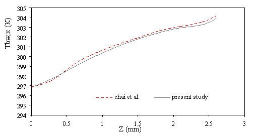
Figure 2. Comparison of the results for average temperature bottom heat sink
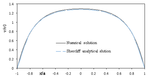
Fig.3 Comparison between numerical and analytical results for flow under magnetic field
Boundary conditions
The set of non-linear elliptical governing equations are solved by using the boundary conditions in the entrance of microchannel (Z = 0),
|
u = 0; v = 0; w = v0 ; T = T0 |
(26) |
at the microchannel outlet (Z = 2.7 mm):
|
|
(27) |
 ; u = 0; v = 0 ;P = Patm
In the left and right sides of microchannel outer adiabatic walls (X = 0 & w):
|
|
(28) |

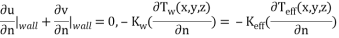
In the microchannel inner walls:
|
|
(29) |
|
|
(30) |

Finally, a constant heat flux condition is imposed at micro heat sink bottom wall (y = 0).
Results and discussion
The variations of pressure drop and Reynolds number for various transverse magnetic fields are shown in Fig. 3a. It can be seen that for a given fluid, the pressure drop increases by increasing the Reynolds number because rising the velocity inlet. As shown in Fig. 3b whit increases intensity uniform and non-uniform magnetic field in the same Reynolds number (Re=300), the pressure drop increases for non-uniform magnetic because the secondary flow near wall became larger and powerful. Also scale up particle diameter of 10nm to 30nm decreasing pressure drop (Fig. 3c).
|
|
|
a) |
|
|
|
b) |
|
|
|
c) |
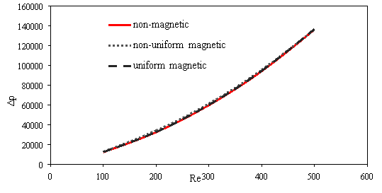
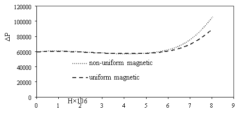
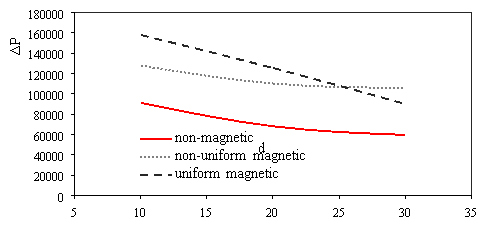
Fig. 3. Effects of various a) Reynolds number [H=6Ã-106, dp=30nm] b) power magnetic field gradients [Re=300, dp=30nm] c) particle diameter [H=8Ã-106, Re=300] on the pressure drop
Fig. 4 presented streamlines for various magnetic fields at 0.0015≤ Z ≤0.002. As shown in Fig.4, when magnetic field is weak the streamlines same together because the magnetic field had not enough powerful for veer stream. By increases intensity magnetic field the nanofluid flow shift to near wall and thereupon the vortex in reentrant cavities became powerful Fig.5.
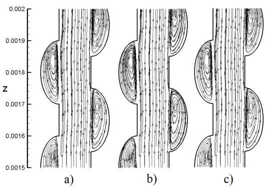
Fig. 4. Stream lines in same Reynolds number (Re=300) and particle diameter [dp= 30nm] for a) non-magnetic field b) non-uniform magnetic field (H=6Ã-106 A/m) c) uniform magnetic field (H=6Ã-106 A/m)
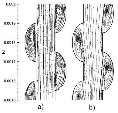
Fig. 5. Stream lines in same Reynolds number (Re=300) and particle diameter [dp= 30nm] for non-uniform magnetic field a) H= 6Ã-106 A/m c) H=8Ã-106 A/m
The friction factor decreases as Reynolds number increases (Fig. 6a). The magnetic field cannot overcome viscous force and affect mean velocity when intensity magnetic field is low, therefor the friction factor is almost fixed for using magnetic and non-magnetic field. Whit increases intensity magnetic field the mean velocity decreases and while the pressure drop increases (Fig. 3.b); therefore, the friction factor increases at maximum intensity field (Fig. 6b). Also scale up particle diameter the main velocity and pressure drop decreases. The uniform transverse magnetic field is depended to velocity that whit decreasing velocity the uniform transverse effect decreases on flow, so friction factor rising (Fig. 6c).
|
|
|
a) |
|
|
|
b) |
|
|
|
c) |
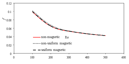
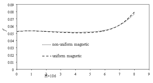
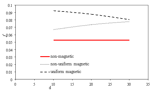
Fig. 6. Effects of various a) Reynolds number [H=6Ã-106, dp=30nm] b) power magnetic field gradients [Re=300, dp=30nm] c) particle diameter [H=8Ã-106, Re=300] on the friction factor
Figure 7 shows the variations of average temperature bottom heat sink for different condition. Whit increasing Reynolds numbers the velocity increasing too and the vortex in reentrant cavities became bigger and powerful, thus average temperature bottom heat sink decreases (Fig. 7a). Effects of various power magnetic field gradients [Re=300, dp=30nm] on average temperature bottom heat sink presented in Fig. 7b. When the intensity magnetic field is weak cannot affect average velocity because cannot overcome viscous force. By strengthening the non-uniform transverse magnetic field the average velocity became larger and growth vortex in channel, therefore average temperature bottom heat sink reduces. Particle diameter rising, the non-uniform transverse magnetic had more effect than uniform transverse magnetic and non-magnetic on average temperature bottom heat sink (Fig. 7c). Whit scale up particle diameter decreasing thermal conductivity and heat transfer for when applied uniform transverse magnetic because it independent of particle diameter.
Figure 8 presented the variations of average Nusselt number for different condition. Nusselt number enhances with Reynolds number in
Cite This Work
To export a reference to this article please select a referencing stye below:
Related Services
View all


DMCA / Removal Request
If you are the original writer of this essay and no longer wish to have your work published on UKEssays.com then please click the following link to email our support team:
Request essay removal