Designing a 1MW Solar Power Plant
| ✅ Paper Type: Free Essay | ✅ Subject: Engineering |
| ✅ Wordcount: 2010 words | ✅ Published: 31 Aug 2017 |
Introduction
CE 1.1 “Turn the air con on, it’s 45 degrees Celsius already”, said my mum. The weariness of stifling heat with the tops of dry 45 degrees Celsius radiated in her tone. But there was no electricity for the past 9 hours. Wretched in the state of disbelief, I realized the painful dilemma of Electricity load shedding was worsening day by day. That’s when I thought to channelize my engineering skills to overcome this issue. And it was back then in 7th Semester of my Bachelors of Mechanical Engineering (University of Engineering and Technology, Lahore) in 2012, I planned to use the scorching heat to produce electricity and design an alternative for the conventional method. I later pitched this idea to my professors who took me under their wings and mentored me to design and present it as a final year project.
I was heading a group of 4 team members.
Background
CE 1.2 During my fifth semester in the university I studied a subject related to renewable energy resources and it fascinated me big time. Most of these resources are environmentally friendly and they would be here to serve us even when the other traditional energy resources would be depleted. Especially in country like Pakistan, it’s the need of hour to explore the renewable resources. Despite having the potential, Pakistan is energy deficient. I decided to work on renewable energy resources during my final year project in an attempt to help the country with potential ways to produce energy.
Nature of project
CE 1.3 The nature of the project was to study the renewable resources currently deployed in the country and the scope of sustainable energy in the country. Particularly, Concentrated Solar Power was the main focus of the project including development of concentrated solar thermal power by using Parabolic Trough Technology.
Objective of the Project
CE 1.4 The objective of the project was to design 1MW solar power plant using parabolic trough technology and help Pakistan to overcome energy crisis by using the economical energy resources.
Nature of My Particular work area
CE 1.5 Being the leader of the group, I had to perform many duties. Some of them are listed below:
- Assigning tasks to team members
- Keep track of the work done by group members
- Arrange meetings between group members and supervisor
- Selection of technology for solar power
- Design calculations
- Report writing
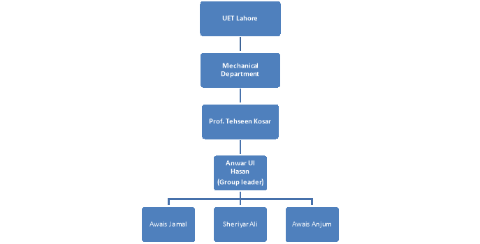
CE 1.6 Organizational structure
Personal Engineering Activity
CE 1.7 After being selected as leader it was my responsibility to start the project right away. So that it could be finished on time. I divided the project into different parts and assigned each part to different member of the group. I had to perform the design calculations and report writing. Other two members had to do literature review, select a storage system and provide conclusion and recommendations.
CE 1.8 To control the overall project it was required to set target dates for each activity, I used Microsoft project to help me in project planning. While assigning the tasks to the members, I also made sure to give them a particular time period to finish each task. After assigning the tasks I kept track of their performances by conducting frequent meetings. If someone was lagging behind, I made sure to help him finish the task within advised time. It helped me a lot to finish the project efficiently before the due date.
CE 1.9 I had to keep the supervisor aware of the progress of project. During the project I had many meetings with the supervisor for the consultation and as well as to report the progress of team members and myself. I had to keep record of all the activities from start of the project till the end and present them to the supervisor from time to time to see whether we were on track or not.
CE 1.10 Basically solar power can be used in two different ways to produce the energy; Concentrating solar power and Photovoltaic. I had to decide which technology we were going to use in our project. The reason behind selecting the concentration technology was that the absorbing materials are more expensive than the reflecting materials. In concentration technology a large surface of reflecting material concentrates the solar power on to a smaller absorbing surface of a collector. Second reason was, due to small size of the collector surface the rate of heat loss from the collector would be low and they can be used at an elevated temperature.
CE 1.11 After selecting the concentrating solar power as main source, I had to pick one of the man ways to concentrate solar power like Parabolic Trough, Solar power Tower, Dish String, Fresnel reflectors. Keeping the local conditions in Lahore in mind and to get a little flexibility I selected parabolic trough. Local conditions in Lahore are much suitable to produce power using a parabolic trough and it could also be used with constant tracking or seasonally adjusted, depending upon the efficiency needed and finances available.
CE 1.12 To begin with the designing, first I had to find the values of enthalpies at different points of the cycle. After that I had to calculate the energy required from concentration and fluid and cooling media flow rates required to produce 1MW electricity. That energy helped me to decide the field requirement and configure solar filed.
CE 1.13 On the basis on the environment locally in Lahore, I had to set some input parameters for the design. The solar irradiation in Lahore was enough to produce the required input temperature and on the base of temperature the value of operating pressure was fixed.
Parameters I used, are given below:
- Power Output at Turbine Shaft
- Steam Pressure to Inlet of Turbine
- Steam Pressure at the outlet of Turbine
- Steam Temperature to Inlet of Turbine
- Specific heat capacity water

CE 1.14 In designing different assumptions were made on the basis of literature review.
Assumptions used in calculations are given below
- Steam Generator Efficiency
 = 85
= 85
- Isentropic Efficiency of Turbine

- Isentropic Efficiency of Pump

- Reflectors & Absorber’s Combined Efficiency

- Land Usage Factor

- Condenser Water Temperature Difference
- Solar Insulation
CE 1.15 After setting all the parameters and assumptions I did Enthalpy Calculations.
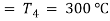
The Rankine cycle and line diagram of such a system are shown below
Figure 1: Real Rankine cycle (non-ideal)
The real life Rankine cycle is composed of 6 processes as shown above in figure 1.
Stage 1-2, boiler increases the fluid temperature and pressure to convert it to a point where the addition of latent heat will lead to the conversion of liquid into wet steam, as shown from point 2-3; Stage 3-4 leads to a pressure increase to convert the wet liquid into superheated steam. After the work done by the steam, stage 5-6, the losses in pressure and temperature due to turbine work leading to the next stage where condensation occurs. The working fluid is heated a bit to improve the efficiency of the system and the cycle is repeated again. The process is illustrated in figure 1.
The figure 2 shows all these processes in a parabolic trough system. From stage 1-2, concentrated solar energy increases the fluid temperature and pressure. Stage 2-3 converts this fluid into wet steam, using solar energy. During stage 3-4, further addition of energy converts the liquid into superheated steam. Pressurized superheated steam expands in a steam turbine which operates a generator to produce electricity. In the last stage, this low pressure and temperature steam, eventually, condenses into fluid again.
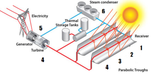
Figure 2: Parabolic Trough System
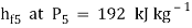
The values of enthalpies and entropies at different temperatures and pressures, at different points in Rankine cycle, were taken from the steam table. The enthalpy of steam at the inlet of steam turbine (h4) at the pressure and temperature values of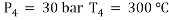
So 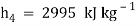
The entropy of steam at the inlet of steam turbine (S4) at the pressure and temperature values of
So 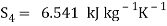
Because the ideal expansion in the steam turbine was Isentropic
So 
The entropy of the steam at the exit of steam turbine can be determined from the formula
Where 
The entropies of steam at the exit of steam turbine (SE) at the pressure value of
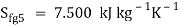
So, by using above given formula, the valve of dryness fraction was

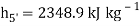
To find the enthalpy of steam at the exit of steam turbine (Ideal), following equation was used
 =
= 
The enthalpies of steam at the exit of steam turbine (SE) at the pressure value of
Then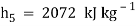
The isentropic efficiency of the steam turbine was given by the following relation
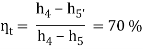
Using equation
The actual dryness fraction  now can be calculated from the following relation
 =
= 
So 
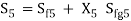
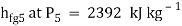
The enthalpy of steam after the condenser at the stage 6 was given by
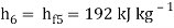
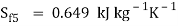
V1 is the specific volume of the saturated liquid taken from the steam table at P5
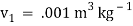
The work of pump was calculated using the formula
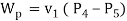
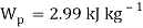
The enthalpy of liquid at the outlet of pump i.e. at stage 1 was given as
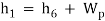
So 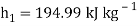
The isentropic efficiency of the pump was given by the following relation
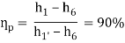
Using above equation, the actual value of enthalpy can be calculated
So 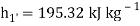
CE 1.16 Using the enthalpies calculated in the earlier step, I calculated the steam flow rate. The energy required to convert the saturated liquid from point 1 into superheated steam to point 4 is given by

The work output/kg of steam flow of the turbine was given by

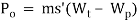
The power output at the outlet of turbine was obtained by dividing the system output by generator efficiency so it was given by
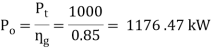
This output was equal to turbine work output/kg of steam flow multiplied by its flow rate so given by the following formula
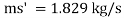
CE 1.17 Steam flow rate was used to calculate the condenser water flow rate.
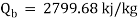
The heat rejected by the water in the condenser/kg of water flow was calculated as:

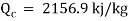
If the temperature differential of inlet and outlet of condenser is  then
then
So, the total energy that we require from solar concentration to generate 1MW electricity was calculated by
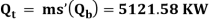
This is the amount of energy we have to produce from the concentration of solar irradiance using solar field consists of reflectors and receivers.
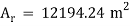
CE 1.18 After calculating the energy required from solar concentration, I used that energy to calculate the size of filed required. I already had the assumed values of solar insulation “G” and combined efficiency of absorber and reflectors . Reflector area
  was calculated using following formula

Where is the reflector area in m2
So
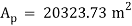
Taking into account the land usage factor Lu=60%

So
CE 1.19 In the last step I calculated the overall efficiency of the plant by taking ratio of power output to power input.
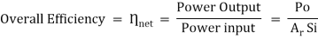
Where 
So the overall efficiency comes out to be

CE 1.20 In safety talks I cautioned my team members to be careful around the hot surfaces. I placed the warning signs near high temperature and high pressure points.I advised my group members to protect their skin by covering it or by using sunscreen, while working outside, so that they could avoid sunburns. Due to these precautions, project was completed without any personal injuries.
Summary
CE 1.21 After all the hard yards of 6 months, I was able to present my design of 1 MW power plant run by solar power aimed to reduce energy deficiency. I presented it as my final year project (combined power point presentation + project report) in front of project supervisor, chairman of mechanical engineering department and an external examiner. It was a stepping stone in power industry in Pakistan. 1 MW power plant can produced sufficient energy to cater for the normal operation of the community households. Moreover, the innovation could not only reduce the global carbon foot print but it could also shift the reliance from already depleting traditional fossil fuel resources. This project helped to understand that its need of the day to switch our focus to renewable energy resources to cope with energy deficiency, more local councils are now encouraging to switch to micro energy renewable resources and design such plants. In the end, I would like to say that it was a great honor for me to see people getting inspiration from my work and using the renewable energy to fix the biggest problem of the country.
Cite This Work
To export a reference to this article please select a referencing stye below:
Related Services
View all


DMCA / Removal Request
If you are the original writer of this essay and no longer wish to have your work published on UKEssays.com then please click the following link to email our support team:
Request essay removal