ABS Brake Model Using MATLAB SIMULINK
| ✅ Paper Type: Free Essay | ✅ Subject: Engineering |
| ✅ Wordcount: 4134 words | ✅ Published: 18 May 2020 |
ABSTRACT
Antilock braking systems are used in new cars to protect the wheels from locking after brakes are applied. The dynamic of the controller needed for ABS system depends on various aspects. The vehicle model frequently is in nonlinear method. Controller desires to provide a controlled torque essential to maintain ideal value of the wheel slip ratio. The slip ratio is characterized in terms of vehicle speed and wheel rotation.
Nowadays, system dynamic equations are described, and a slip ratio is stated in terms of system variables namely vehicle linear velocity and angular velocity of the wheel. By applying an unfairness braking force system, response is obtained using Simulink models. Using the linear control approaches like P – type the effectiveness of maintaining desired slip ratio is tested.
Figures List
|
No. |
No. |
Name |
Page No. |
|
1 |
3 |
Quarter Vehicle model |
2 |
|
2 |
3.1 |
The µ-slip curve. |
5 |
|
3 |
3.2 |
Slip ratio with coefficient of friction |
7 |
|
4 |
3.3 |
Feedback Control Diagram |
7 |
|
5 |
3.4 |
Diagram of Equations (dynamics) |
9 |
|
6 |
3.5 |
Slip Ratio subgroup |
9 |
|
7 |
3.6 |
Coefficient Friction Subgroup |
9 |
|
8 |
3.7 |
Modified Feedback Control Vehicle Model |
10 |
|
9 |
3.8 |
P-type Feedback control |
11 |
|
10 |
4.1 |
Time vs Slip ratio |
13 |
|
11 |
4.2 |
Time vs Stopping distance |
13 |
|
12 |
4.3 |
Slip ratio without Abs System |
14 |
Chapter 1. Basic Introduction
Anti-lock brake systems avoid brakes from locking throughout braking. Below braking environments, the driver controls the brakes. Nevertheless, during severe braking and on greasy roadways, when driver origins wheels to approach lockup, the ABS system takes over. ABS moderate the brake line pressure autonomous of the pedal force, to take the wheel speed back to the slip level range that is compulsory for best braking performance. The ABS system consists of wheel speed sensors, a hydraulic modulator, and an electronic control unit. The ABS have a response control system that modulates the brake pressure for wheel deceleration and wheel angular velocity to avoid the controlled wheel from locking. The system shuts down when the vehicle speed is below a pre-set threshold.
The objectives of ABS systems:
1. To decrease stopping distances,
2. To progress stability, and
3. To recover steerability through braking.
Stooping Distance: the distance to a stopover is a purpose of the mass of the vehicle, the more velocity, and the braking power. By exploiting the braking force, the stopping distance will be minimalized if all other issues persist continuous. Nevertheless, on all types of exteriors, to a greater or less, there exists a peak in fiction constant. It follows that by keeping all the wheels of a vehicle close the peak, an ABS system can attain a supreme fictional force and, consequently, the smallest stopping distance. This objective of ABS systems, though, is strengthened by the need for vehicle stability and steerability
Stability: Even though slowing and stopping vehicles constitute fundamental reason of slowing systems, extreme friction force may not be desirable in all belongings, for example not if the car is on a so-called p-split surface such that meaningfully more braking force is obtainable on one side of the vehicle than opposite. Put on maximum braking force on sides will outcome in a yaw instant that will tend to pull the vehicle to the friction side and donate to vehicle instability and forces the operator to make extreme steering corrections to respond the yaw moment. If an antilock system can maintain the slip of both rear wheels at the level where the lower of the two friction factor’s peaks, then lateral force is reasonably high, though not maximized. This event contributes to stability and is an objective of antilock braking systems.
Steerability: Moral peak frictional force controller is essential to achieve fitting crosswise forces and, consequently, fitting steerability. whereas braking is important not only for slight course corrections but also for the possibility of steering about an obstacle. Tire characteristics play a significant role in the braking and steering answer of a vehicle. For ABS-equipped vehicles the tire act is of critical significance. All decelerating and steering forces must be produced within the small tire contact patch amid the vehicle and the road. Tire traction forces as well side forces can only be formed when a difference exists among the speed of the tire circumference and the speed of the vehicle qualified to the road surface. This modification is denoted as slip. It is joint to relate the tire braking force to the tire braking slip. Later the peak value has been reached, improved tire slip causes decrease of tire-road friction coefficient. ABS must limit the slip to values below the peak value to avoid wheel from locking. Tires with a high peak resistance point achieve extreme friction at 10 to 20% slip. The best slip value reductions as tire-road friction declines.
SCOPE & OBJECTIVE OF PRESENT WORK
Throughout design of Anti-lock Braking System, non-linear Automobile dynamic forces and unfamiliar condition Additionally boundaries, modification because of mechanical wear essentially be leisurely.
The work is to find out the exact value and slip ratio for with ABS and without ABS o that can we can compare both ratio and find out accurate result for that purpose need to use quarter vehicle model and once get the result then simulate the brake system for getting slip ratio
Basically, we can do Simulate with 4 types of control strategies, but I used which I bold below
Proportional Feedback control
- Proportional Derivative Feedback Control
- Proportional Integral Feedback Control
- Proportional Integral Derivative Feedback Control
At the end, once compared both ratios we come to possible result.
All model is encouraged from the sample model of ABS provided that in MATLAB Simulink software.
Chapter 2. Historical review
Anti-lock braking system development, that’s the one which is outstanding safety features, as result in 1952 ‘maxaret’ for air craft ,England in 1972, the Jensen interceptor automobile was the first manufactured car offer maxaret based Anti-lock braking system using propeller shaft speed sensor and coupling, and that time United states was working with different kinds of production companies for make Anti-lock braking system and finally in 1969 ford manufactured rear wheel Anti-lock brake thunderbird offered by Kelsey Hayes
After that, Bendix manufactured 4 wheels anti lock braking system for some luxury models then GM (General motors) like tornado and fleet wood. In 70s all production companies used the state-of-the-art components like vacuum parts for energy sources and analog electronics components
In the 70s NHTSA (National Highway and traffic safety Administration) United states department of transportation allotted regulation which is Anti lock brake must for trucks and trolleys by 1975. After some time, NHTSA cause of breakdown of anti-lock braking system 41% of sensors, 16% ABS valves, 8% of computers 3% manpower mistakes.
In Europe mid-’70s, brake and hardware vendors had set up computerized gadgets fluctuating from simple parts to microchips. in, 1978. This four-wheel add-on framework was introduced in the rest of the vacuum or pressure driven lift framework. BMW and others pursued in no time. Japanese brake and vehicle makers presented ABS brakes dependent on the Bosch framework just as their very own structures by the mid-‘ 80s. The Bosch ABS was utilized in the ’86 Corvette and Cadillac All ante. In 1984 an incorporated ABS created by ITT-Tevez was presented on the Lincoln Mark VII in the U.S. what’s more, in 1985, as standard gear on the Ford Scorpio in Germany. The Tevez coordinated framework joins the ABS actuator aeraulic promoter and ace chamber into one unit. The Tevez ABS framework was in like manner accessible on extravagance GM vehicles in the ’86 model year.
Chapter 3. Mathematic Model Methodology
3.1 DYNAMICS OF VEHICLE
Essentially, the vehicle model which includes entirely applicable appearances of the vehicle is much complex to use in the control system structural. So, for explanation a model catching the important features of the Automobile system must be hired for making design of controller. The design measured below just like a quarter vehicle model.
Apparently, same model used for make the controller.

Fig.3: Quarter Vehicle Model
The velocity of the car and the speed of rotating of the wheel establish the grades of autonomy for the model. The governing two calculations for the signs of the model are as follows:
Balancing brake force in longitudinal direction
 ….1
….1
Sum of torque on center (wheel)
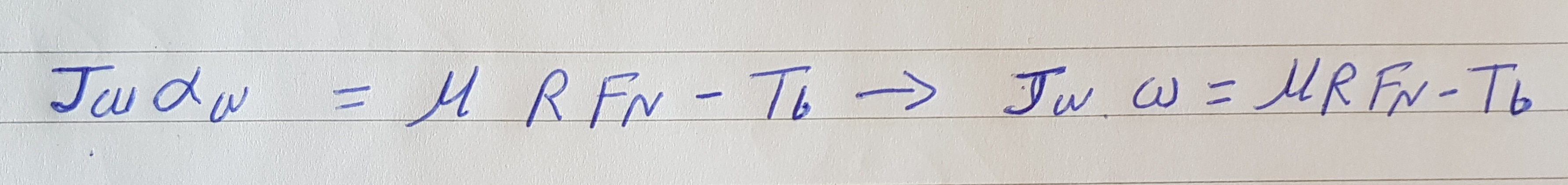 ….2
….2
Defined slip ratio
 ….3
….3
Distinguishing on mutually sides
 ….4
….4
The terminology in equations is presented
vx = Vehicle linear velocity
ax = vehicle acceleration
w = wheel speed
Tb = braking torque
aw = angular acceleration
µ = coefficient of friction
R = tire radius
X1 = X2 ….5(1)
X2 = Vx ….5(2)
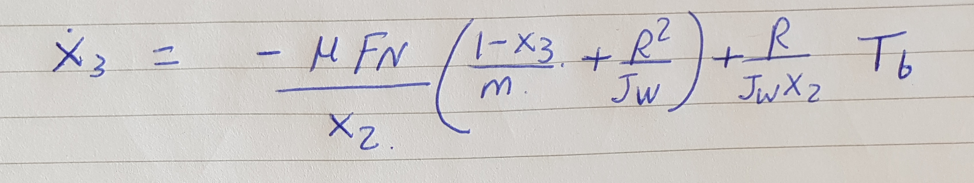
X3 =
….5(3)
Sx Is distance of stopping
 ….6
….6
 ….7
….7
 ….8
….8
With control the torque of braking and when test is evaluating Anti lock braking system performance with proportional type of controlling system.
3.2 PROBLEM FORMULATION
The relative coefficient of friction contrasted with slip ratio, delivers the clarification of the ability of Anti lock Braking System to preserve Automobile steerability and stability, and unmoving making shorter stopping distances than those of locked. The coefficient of friction can differ in a identical range, which dependent on some factors like:
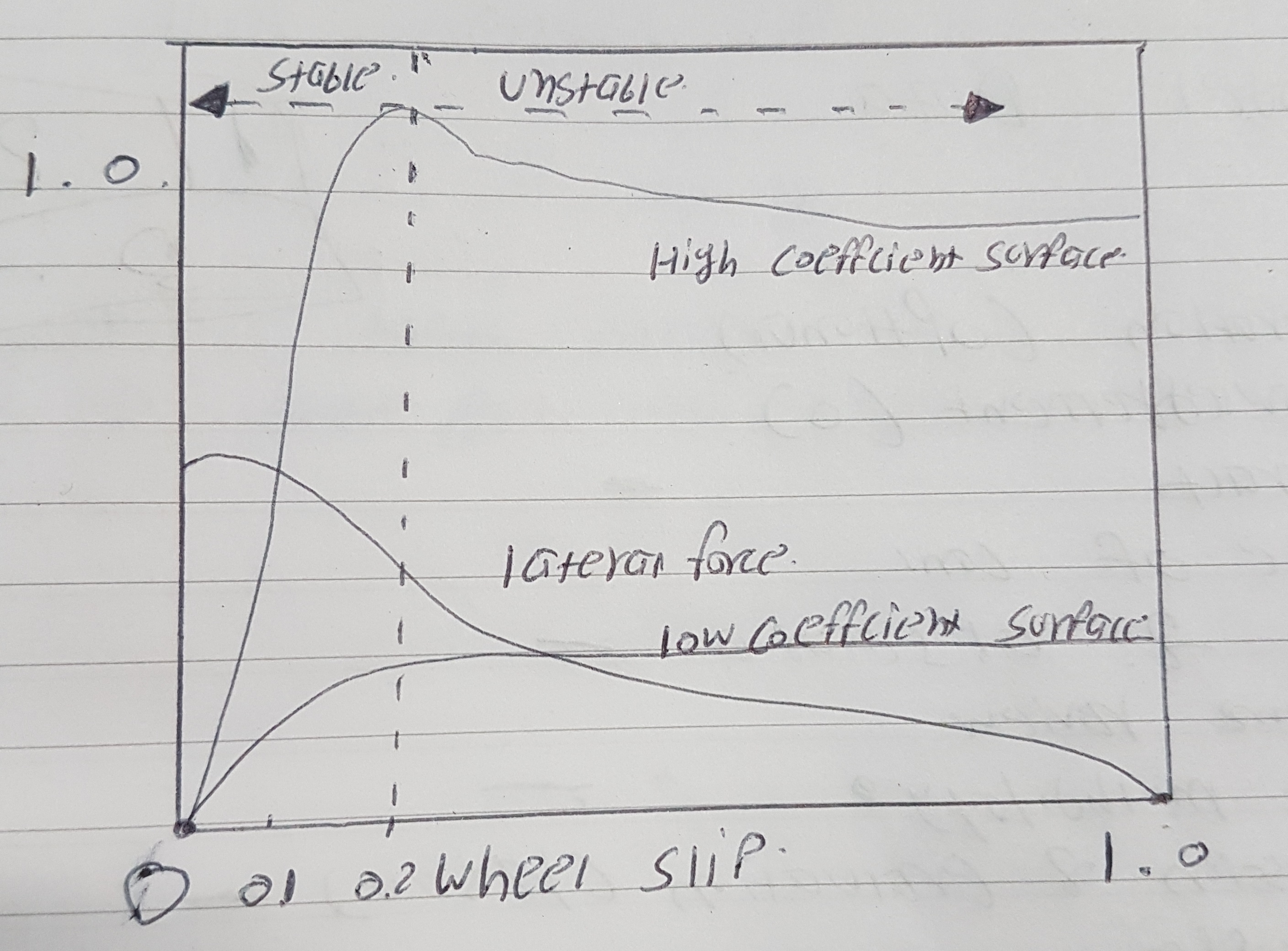
Fig 3.1: The µ-slip curve.
Road condition
Side angle of tire
Brand of tire
Speed of vehicle
Ration of slip between road and tire surface
 9
9
Like,
c1 is friction curve value
c2 figure of friction curve
c3 difference friction curve
c4 typical value of wetness.
for dry surface parameters are
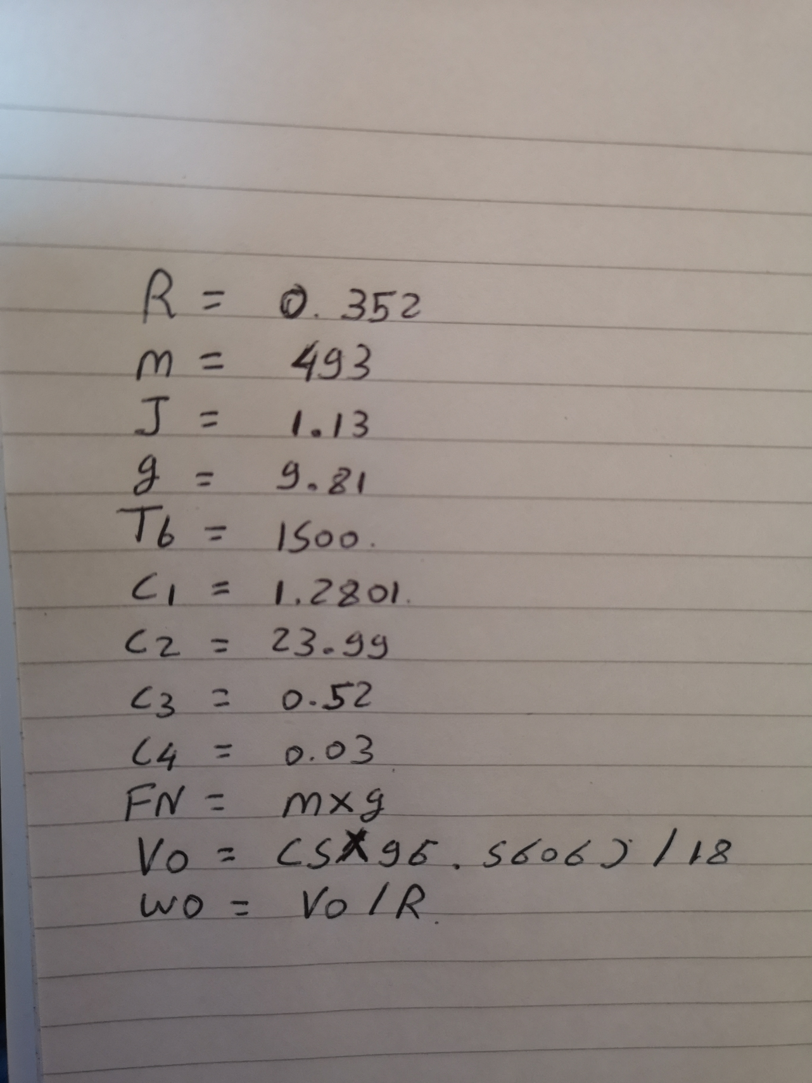
c1- 1.2801, c2 – 23.99, c3-0.52, c4 – .03
The friction coefficient in between the tire and surface which has an extremely value at the slip ratio of wheel. Significantly numbers based to the road type. Like we seen Fig 2.2, surfaces of road coefficient of friction numbers is extreme when slip ratio is roughly 0.2 and can be worst when slip ratio is 1 in in other hand when wheel is locked. So, neutral of the Anti-lock Braking System regulator is to regulate slip ratio to the target of 0.2 to maximize the coefficient of friction for any given road surface.

Fig3.2: slip ratio vs coefficient of friction
3.3 CONTROL SYSTEM
The system of control is a locked loop system and sensor screens the output and forages data to the and alters the control as essential to preserve the anticipated system output. Fig shows the block illustration of the feedback system.

Fig3.3: FEEDBACK CONTROLLER DIAGRAM
- Proportional Control
A proportional controller effort to control the yield by applying input to the system which is in quantity to measured error amid the output and the set-point. Currently control torque is

where kp is proportional gain the controller.
e = gema D – gema
Significantly, gema D is predicted result and Gema is real output measured by sensor.
3.4 SIMULINK MODEL
Quarter vehicle Simulink model
To model the Anti lock Braking System with other controller system uniting the dynamic equivalences is modelled in MATALB Simulink environment. Fig shows the diagram with some dynamic equation as we considered in first paragraph.

Fig 3.4 Diagram with equations (dynamics).
To model this system in MATLAB Simulink or any designing software, there are lots of subgroups to avoid confusion. Slip ratio calculation given in Equation no. 9 and it can be look as subgroup shown in figure


Fig 3.5 slip ratio subgroup
As well as there is one subgroup which is frictional coefficient.


Fig 3.6 Coefficient of Friction subgroup
Simulink model of ABS using proportional feedback control
Fig 3.7 present the modified diagram there is one SUM box in between brake torque and input terminal . So, the total torque input T to wheel is
T = u + Tb (15)

Fig 3.7 Modified Feedback Control Vehicle Model.


Fig 3.8 P-type Feedback control
Chapter 4. RESULTS & DISCUSSION
4.1. USED PARAMETER
For simulate the concert of different car parameters with or without any control system under traditional line braking resulting used parameters are below.
I wanted to attach my parameter from MATLAB Simulink software but unfortunately my MATLAB license I expired so I noted down all parameters see the image below which shows all parameter which I used to make this model.
4.2. PROPORTIONAL CONTROL
When controller is merged in the system to sustain persistent ratio of slip modest linear model named P type control with a relentless gain kpcomes first.
Fig 4.1 and Fig 4.2 shows graph of ratio of slip vs time and stopping distance vs time respectively.

Fig. 4.1-time vs slip ratio

Fig. 4.2-time vs stop distance
Compare stop distance and growing ratio of in loop case, P type – controller materials governor force and continue ratio of slip at 0.01state error and the stop distance decreased.
4.3. Without ABS System Model
If vehicle is not assembled with Abs System. Then it will directly be forced to clamp with disc through wheel and consequently it can damage tyre and some chance for accident as well.
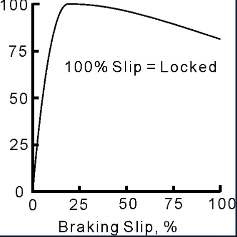
Fig 4.3 Slip ratio without Abs System
It may put in critical condition.
4.4. Discussion
ABS improve braking performance of vehicle. slip ratio v/s time graphs suggests that a proportional controller will have the effect of reducing the rise time and will reduce but never eliminate the steady–state error. And significantly, reducing the overshoot and improving the transient response.
Chapter 5. CONCLUSION
 To conclude the statement is made for undertstand application of different kinds of controller used to make Anti lock braking system. As you can see that Whole system made from quarter model of car and equations are formed and model made to shows the diffrence between Anti lock braking system and any other brake system anti lock braking system perfoming more instand braking with short priod of time and small stopping distance and it matters for tyre surfaces as well because it improves tire life compare to any other brake like disc brake or drum brake graph starightly says that that makes curve to stop the vehicle than other brakes are making angle in graph the whole process done in Matlab simulink to get accuracy in the model and we can use any other controller like PD type controller , PI type control or PID type controller these all are stretegies we can use to find out the result.
5.1. FUTURE SCOPE
Significantly, we can go further for this system like use different strategies and after that we can find out the accurate result with neat graph and once you get the result we can use in our vehicles and even we make more better by using linear and nonlinear strategies for any vehicle.
Chapter 6.
Project management / Risk management / Key skills development
6.1Project management
During my Project, I am managing my project very well and significantly I keep in touch with my tutor like once in month and I done very well but when I started to design the model it makes confused sometime because of the different version of MATLAB because that time I was working with 3 different version Matlab16 Matlab17a Matlab18b.
Sometime model was not run and sometime showed syntax error so that is why I extend my project for 10 days. But I set my project activity by weekdays. So it became easier for me.
6.2Risk management.
There are not as much risks like hardware project but still I am scared when MATLAB showed me syntax error because sometimes, they changed their parameter by itself. So, I need to start from beginning after that I created variables, so these kinds of risks occur every week, but I managed by creating variables.
And one-time power cut was happened with my laptop so after that I keep my file in mail and pen drive.
6.3Key skills development
Honestly, I learned a lot during this project, and it makes me tough because every week I am facing new error so that was created patient in my mind.
And I learned so many functions in MATLAB like
Creating variables
Dashboard scope
Creating C and C++ code
Equation generating
Controller tuning.
How Abs system is working and how it defers to wheel how it reduced speed how slip ratio reduced.
References
|
Sr no. |
Book name |
Author name |
|
1 |
A novel method for non-linear control of wheel slip in antilock braking systems |
H. Murrained, M. Mirzaei |
|
2 |
Control Engineering Practice |
H. Mirzaeinejad |
|
3 |
Robust control of anti-lock brake system Vehicle |
S. baslamisli, I. Kose |
|
4 |
Antilock Brake System with a Continuous Wheel Slip Control. |
S.B.Choi |
|
5 |
IEEE Transactions on Control Systems Technology |
IEEE |
|
6 |
SIMULINK model of a quarter-vehicle with an anti-lock braking system |
K.Z. Rangelov |
|
7 |
MODELLING_and_DEVELOPMENT_OF_ANTILOCK_BR.pdf |
|
|
8 |
||
|
9 |
||
|
10 |
https://www.mathworks.com/matlabcentral/answers/398846-anti-lock-brake-system |
|
|
11 |
||
|
12 |
MATLAB and Simulink: modeling dynamic systems |
Abell J |
|
13 |
Modern control design with MATLAB and Simulink |
Tewari, Ashish |
|
14 |
MATLAB programming for biomedical engineers and scientist. |
King, Andrew P, |
|
15 |
Science Technology, vol. 24 |
|
|
16 |
Modular design and testing of antilock brake actuation and control using a scaled vehicle system. |
C. B. Patil and R. G. Longoria, |
SIMULINK Modelling and Performance Analysis for quarter vehicle Antilock Braking System
Abstract:
Over the past years, the automotive industry has undergone a significant amount of change. Despite the fact that Anti-Lock Braking System has already been implemented in modern cars, the technology is still needing to be addressed due to the non-linear characteristics and model uncertainties in vehicle dynamics. The ABS control systems fail to attain satisfactory performance with respect to tyre characteristics and bad road-conditions. It is important to improve the ABS performance in the areas of stability, steerability and stopping distance. In this project proposal, we present a mathematical model of quarter vehicle and implementation of ABS modelling using MATLAB Simulink. We apply linear control strategies to validate the effectiveness of maintaining desired slip ratio in the results.
Introduction:
Anti-lock braking system (ABS) is an automobile safety system that allows the wheels of the vehicle to maintain contact with the road surface according to driver inputs while braking, preventing the wheels from locking up and avoiding uncontrolled skidding. ABS offer improved vehicle control and minimizes the stopping distances on dry and slippery surfaces. ABS modulate the brake line pressure independent of the pedal force, to bring the wheel speed back to the slip level range that is required for optimal braking performance. The principal ABS components are hydraulic modulators, wheel speed sensors, ECU for signal processing and control and triggering of the signal lamp and of the actuators in the hydraulic modulator. ABS control systems extend to a wide range of issues and challenges.
Objectives:
To prepare detailed literature on various existing ABS Models
To identify problems and challenges in the existing techniques associated with stopping distance and slip ratio
To propose a solution that will target to improve the ABS performance
To implement Antilock Braking System Modelling using MATLAB/Simulink
To make use of the tire and ABS models developed previously for a quarter car application
To apply linear control strategies like P – type to test the effectiveness of maintaining desired slip ratio
To simulate the performance of different vehicle parameters with and without any feedback control system under straight line braking
To validate the proposed ABS control system and its result parameters
Project Methodology:
The ABS will be implemented on a one-wheel quarter-vehicle model and evaluated for an emergency straight-line braking maneuver on a high-friction surface. Simulation will be carried out to achieve a desired slip factor with control scheme such as P – type. ABS with different controller’s system will be modelled in Simulink environment. In this project, system is nonlinear model and controller is a linear.
Risk Assessment:
|
RISK |
Possible Solutions for the risk |
Probability of Risk |
|
Insufficient background work due to less reference materials |
Accessing IEEE / ACM Journals with memberships and Data gathering from Open Access Journals, search engines, etc. |
Low |
|
Complexity while Modelling the ABS |
Meeting the project supervisor for guidance |
Moderate |
|
Developing control strategies and modelling of tires in MATLAB/ SIMULINK may take long time. |
Consistent self-learning and discussions with the project supervisor to meet the deadlines |
High |
|
Working with MATLAB/SIMULINK Tools |
Finding an Academic Licensed tool from MathWorks and make use of self-learning Video demos and online help for executions. |
Low |
Skill Development:
To learn modern automotive vehicle braking, tire-to-road interface, vehicle dynamics during braking and the components of a brake system
To build skills and practical knowledge of Modelling & Simulation using MATLAB SIMULINK
To have deeper understanding of what is System, Model, Simulation and Mathematical Modelling
To using the knowledge of control system & mathematics how to develop a model.
Appendix B Gannt chart

Cite This Work
To export a reference to this article please select a referencing stye below:
Related Services
View all


DMCA / Removal Request
If you are the original writer of this essay and no longer wish to have your work published on UKEssays.com then please click the following link to email our support team:
Request essay removal