Computer Aided Engineering and Product Manufacture
| ✅ Paper Type: Free Essay | ✅ Subject: Design |
| ✅ Wordcount: 1193 words | ✅ Published: 23 Sep 2019 |
Introduction
The main goal of this project is to perform a two-mold design and analysis. The purpose is to design a part and mold gates, to simulate the designed geometry in CREO Parametric 3.0 and to improve the design in order to achieve the most effective manufacturing scenario.
The selected artefact is a pet’s bowl. In this report, the model of pet’s bowl will be designed and improved by applying draft angles and rounds. Then it will be simulated in the Plastic Advisor tool of CREO software. This analysis will reveal the best place for the material injection and material type. After that, two gates will be designed for molding process with calculation of required clamp force for the injection pressure of 100 MPa. On the final stage, the appropriate manufacturing technology will be applied and simulated in CREO software. Final results of machining time and appropriate cutting parameters will be discussed further in the report.
Model design
The initial design (Figure 1) represents a simple pet’s bowl with two separated zones for different type of food. The external shape of the bowl is 6×6 in square.
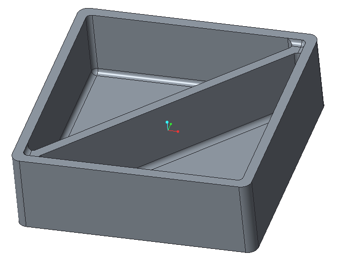
Figure 1 – Initial design
The drawing with all dimensions is shown on the Figure 2, below:
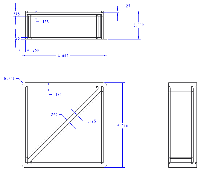
Figure 2 – Drawing
Model modification
For easiness of part removal from molding die drafted angles and rounds were applied to the model.
The updated part has a 5 degree drafted angle (Figure 3).
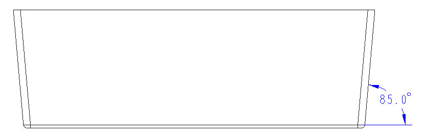
Figure 3 – Updated part
All rounds/fillets are shown on the Figure 4, below
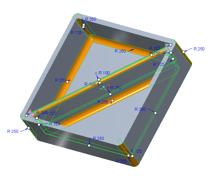
Figure 4 – Rounds/fillets
The final design is shown on Figures 6 – 7:
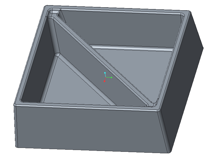
Figure 6 – Final Design, front view
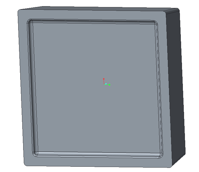
Figure 7 – Final Design, bottom view
The integrity can be checked by calculating the volume. If the model has some issues with the integrity, the volume calculation will fail. As can be seen from Figure 8, the integrity of the part is satisfied.
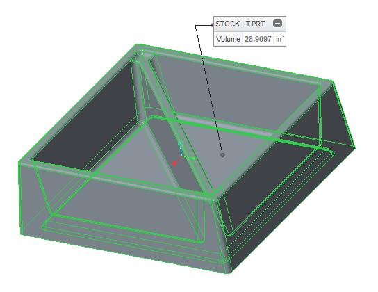
Figure 8 – Volume, in3
Plastic Advisor Calculations
The next step is the material selection. The assumed material for the first iteration is Polyphenylene sulfide (Ryton R-7). All material properties are shown on the Figures 9 – 12.
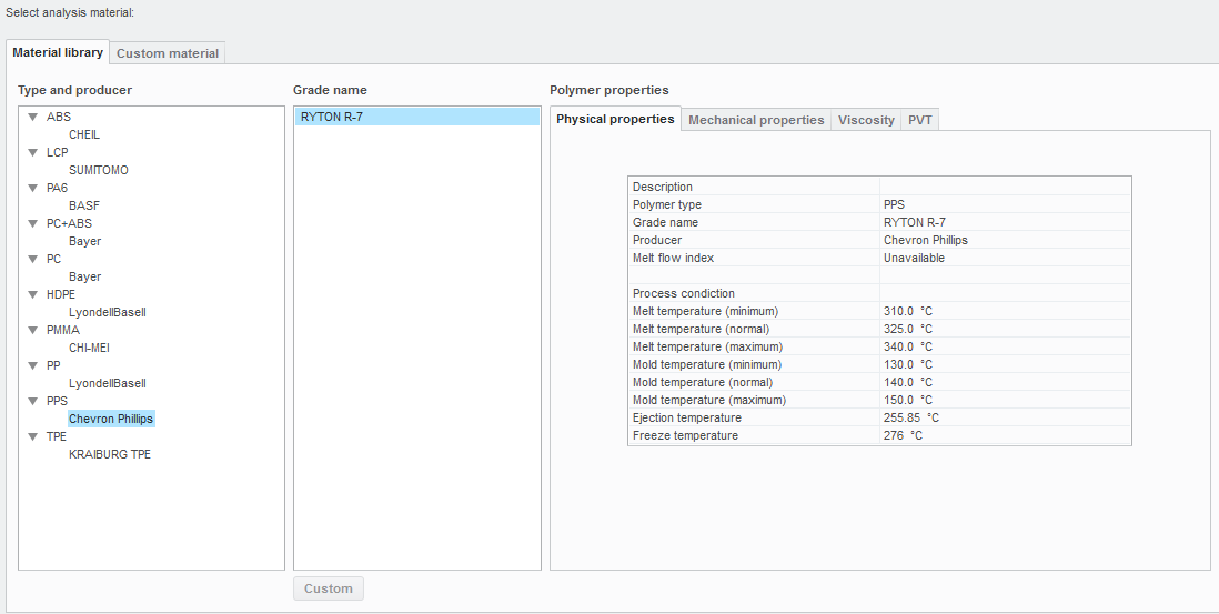
Figure 9 – Physical properties
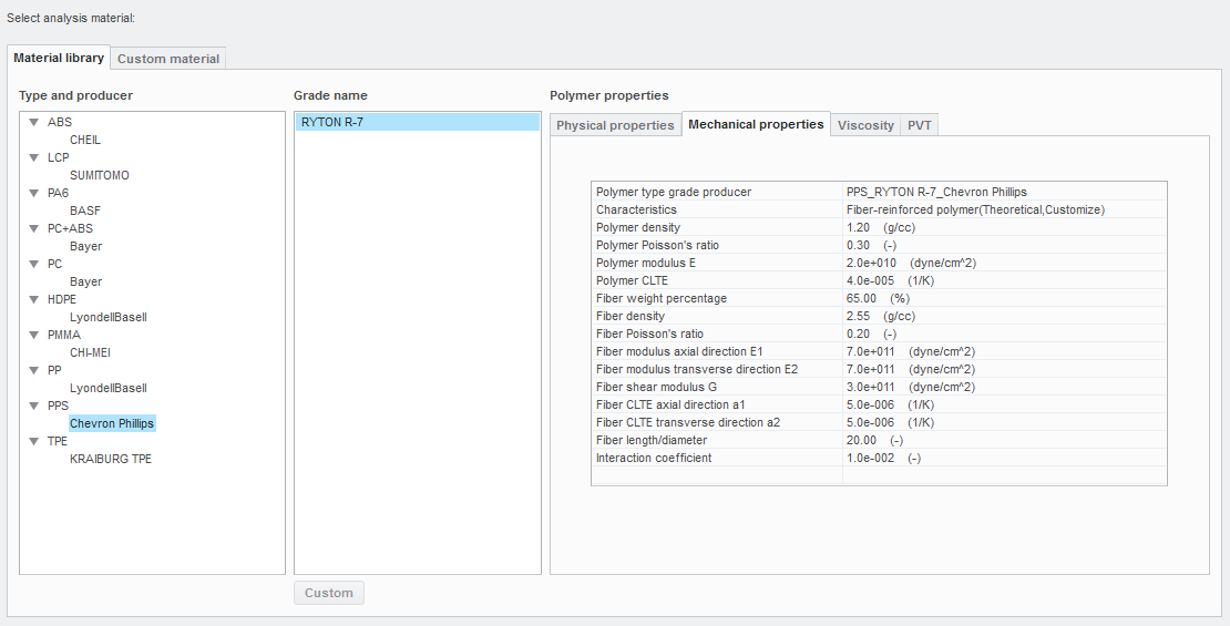
Figure 10 – Mechanical properties
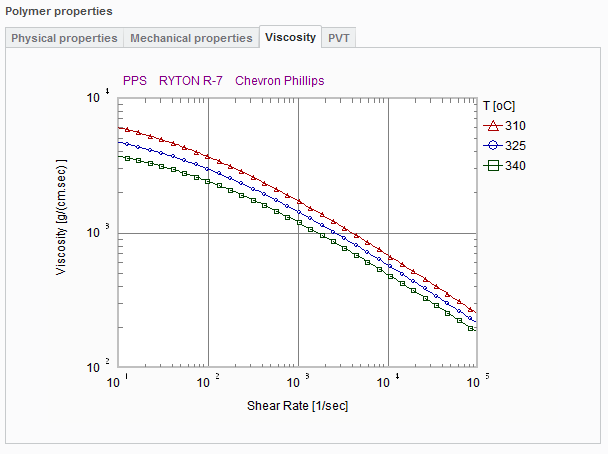
Figure 11 – Viscosity
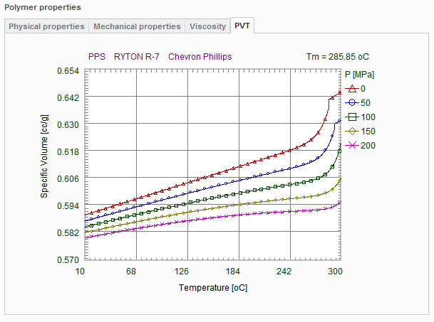
Figure 12 – PVT
After running the Plastic Advisor simulation, the most effective place for injection can be found (Figure 13).
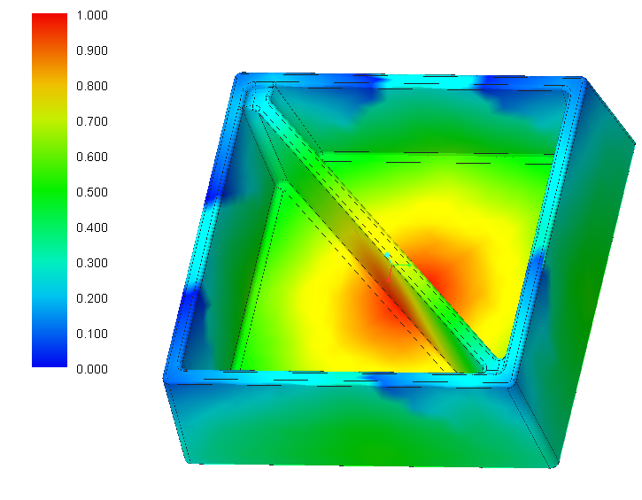
Figure 13 – Plastic Advisor simulation
As can be seen, the best place to start filling the material is located at the bottom center of the detail.
The further simulation will be performed in order to obtain a melting time distribution. Analysis setup is shown on the Figure 14.
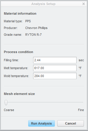
Figure 14 – Analysis setup
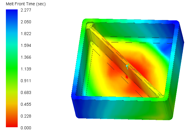
Figure 15 – Melt front time, sec
As can be seen from Figure 15, the maximum melt front time is 2.277 sec. Since all results are satisfactory, it allows us to apply the selected material for mold operation. Thus, the selected material is Fiber-reinforced polymer (Ryton R-7).
Molding dies design
In order to create the gates with exactly the same cavities, the material of the part can be subtracted from the enclosed mold. This operation can be performed in Assembly by using “cut out” tool (Figure 16).
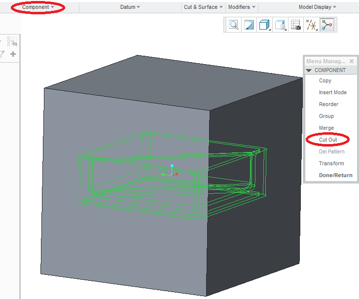
Figure 16 – Cut Out operation
Mold parts
The final design for the mold parts is shown on Figures 17 – 18.
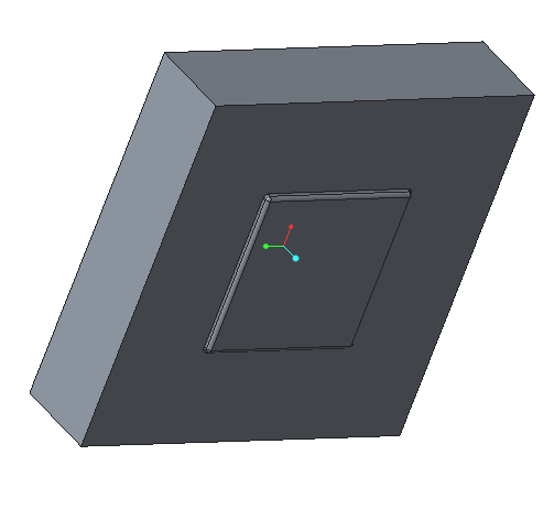
Figure 17 – Upper gate
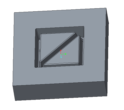
Figure 18 – Lower gate
Mold calculations
The Shrinkage:
As the plastic is molded while being hot, the molded stock should have larger dimension in order to conform needed dimensions when cooling down. According to Polyphenylene Sulfide (PPS) Typical Properties Generic PPS [1], the maximum molding shrinkage is 2.3%. This value was used in the shrinkage calculations. Shrinkage was applied to the geometrical dimensions of the part (like height, wall thicknesses, etc.).
Height of the stock part:

Wall thicknesses:

Base thickness:

The height was increased proportionally to its upper and lower parts (above and below the base). The wall thicknesses were increased symmetrically. The base thickness was increased inside.
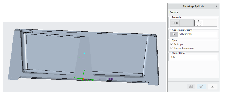
Figure 19 – Shrinkage Ratio and Draft Angles (cross-section)
The Required Clamp Force:
The area has a value of 
The required clamp force can be found from the injection pressure by the following formula:

Where 
The clamp force will be:

The bolt’s material was taken – Alloy steel (quenched and tempered) [4]. Tensile strength is 1220 MPa.
The load for a single bolt can be approximately taken as 600 kN (total load divided between four bolts). The minimum necessary bolt diameter can be found from the following formula:

The updated design for mold dies is shown on the Figures 20 – 21.
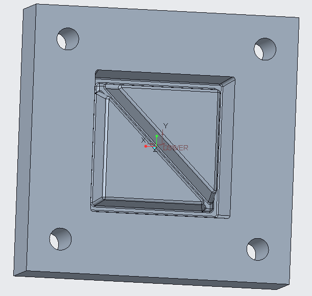
Figure 20 – Lower gate with bolt holes
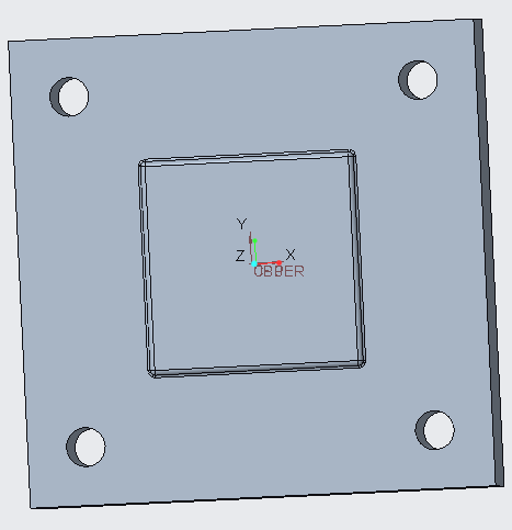
Figure 21 – Upper gate with bolt holes
Molding Die Manufacturing Technology
The molding die is produced from mild steel plate. The dimensions for the upper plate are 12″×12″×2.9″. For the lower plate are 12″×12″×3.2″. The cavities will be milled with the following polishing of the surfaces that are in contact with the stock.
Milling of the main cavities will be done with a mill made of high speed steel. Appropriate cutting speed for milling mild steel is 30 m/min. Drilling of the bolt holes will be done with a drill made of high speed steel with appropriate cutting speed of 30 m/min [1].
Depth of cutting of mild steel was taken 0.03″ [2].
The above values are for rough shape. For fine surface finishing the following values were chosen: cutting speed is 10 m/min, depth of cutting 0.01″.
After fine surface finishing, surface polishing will be done and reaming the bolt holes.
The mold analysis is shown on the Figures 22 – 25.
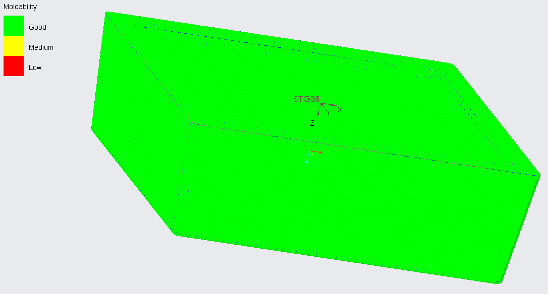
Figure 22 – Moldability Analysis
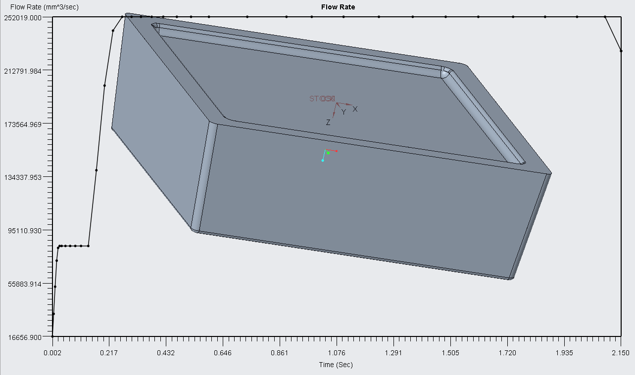
Figure 23 – Flow Rate
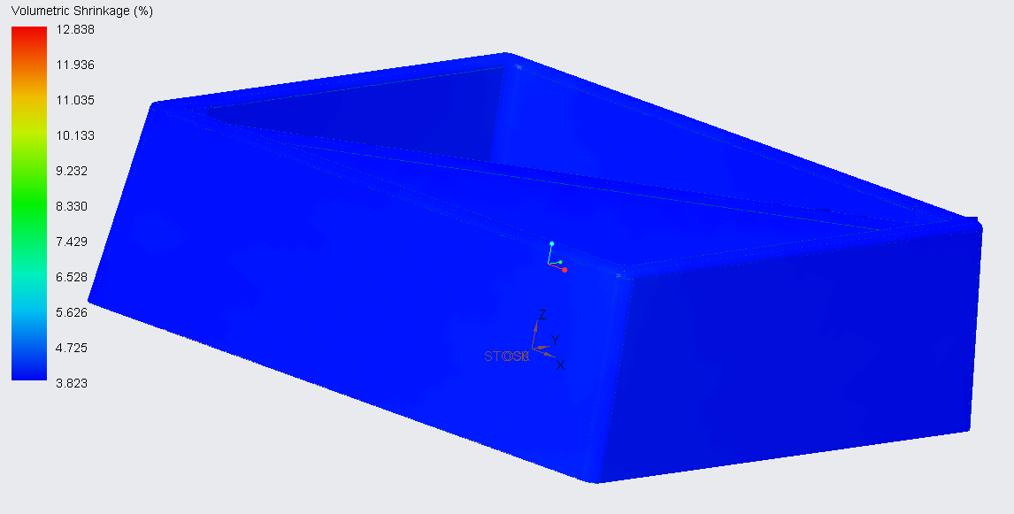
Figure 24 – Volumetric Shrinkage
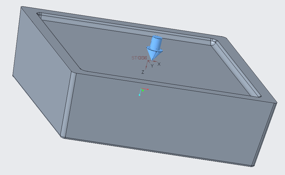
Figure 25 – Injection Gate Location
Logo (the student’s number) will be engraved on the upper molding die with a CNC mill (Figures 26 – 27).
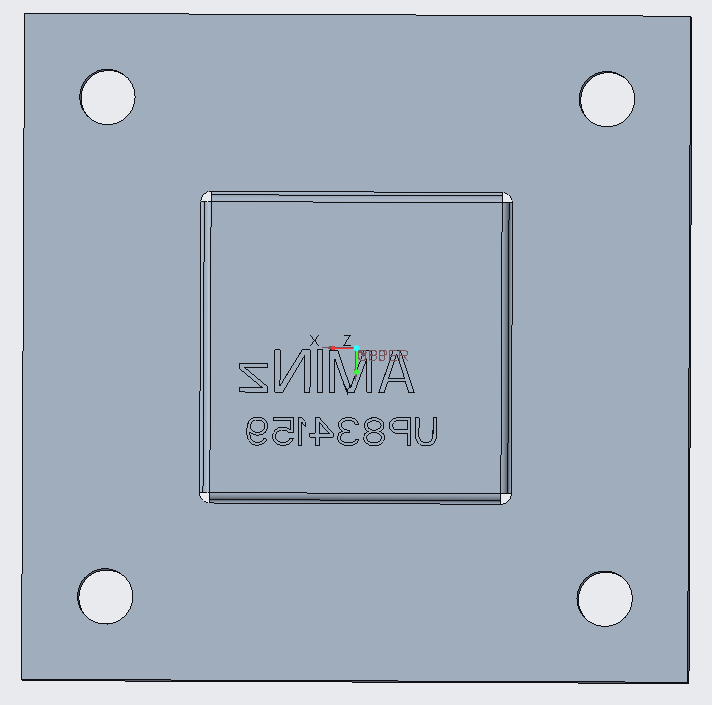
Figure 26 – Logo Engraving
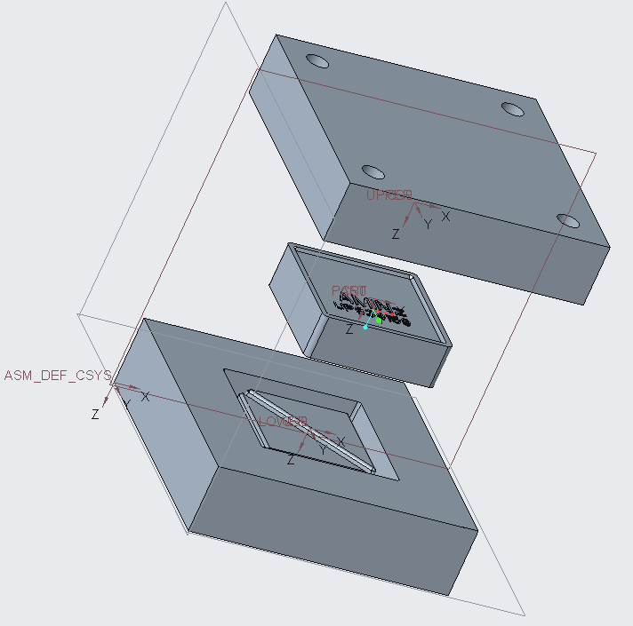
Figure 27 – Complete View on Molding Form and Part
0.25 inch diameter for a mild tool was used in CREO simulation (Figure 21). Milling analysis settings are shown on the Figure 22.
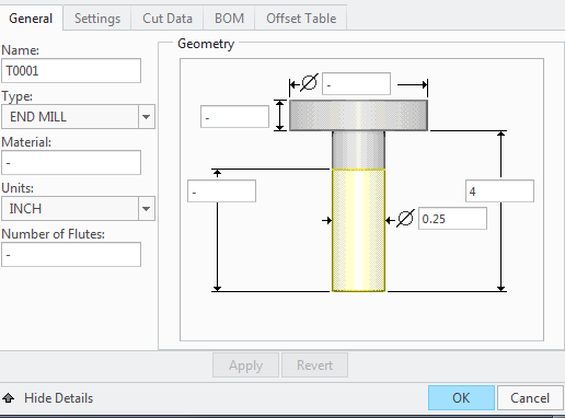
Figure 21 – Mild Tool
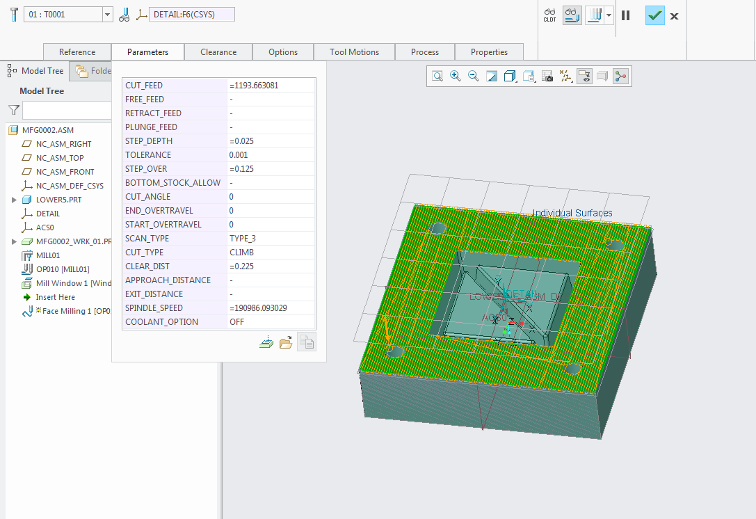
Figure 22 – Milling analysis settings
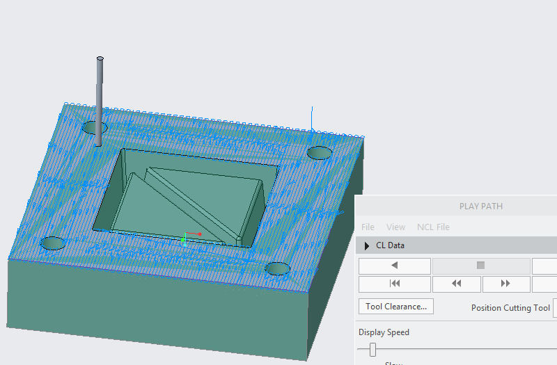
Figure 23 – Milling operation on external surface
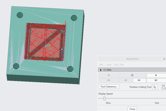
Figure 24 – Milling material removal from internal part
Figure 23 – 24 show the milling simulation for lower part in the CREO software. The similar operation was used for the second die part (upper part).
Alternative Molding Die Manufacturing Technology
As an alternative method of manufacturing of a molding die, die forging can be used. It will shorten production time significantly. But this method is not appropriate for single-piece manufacture as it will cost too much.
Conclusions
As was shown during this project, the bowl was successfully designed and simulated, by using all technological steps required for manufacturing. Both mold dies were obtained by using milling operation and special surface treatment. The stock detail can be manufactured by using mold technics that was successfully verified during the simulation in CREO software. The alternative way for die manufacturing can be a die forging. However, this approach is more expensive and is efficient only for mass production.
The final design is shown on Figure 25, below:
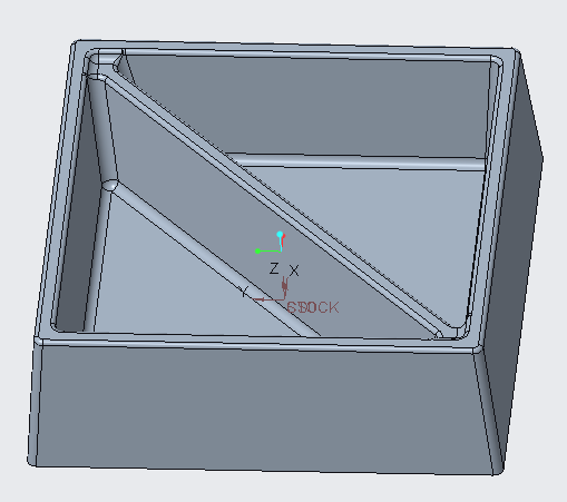
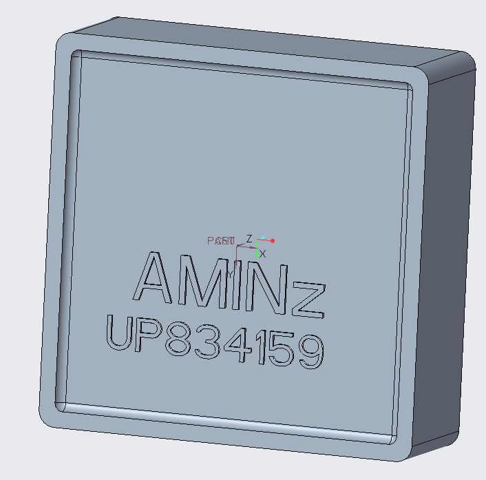
Figure 25 – Final design, a) front view, b) bottom view.
References
[1] Etantdonnes.com. (2018). Cutting Speeds. [online] Available at: http://www.etantdonnes.com/MACHINE/TABLES/cuttingSpeeds.html [Accessed 20 Jul. 2018].
[2] Plastics.ulprospector.com. (2018). Polyphenylene Sulfide (PPS) Typical Properties Generic PPS | UL Prospector. [online] Available at: https://plastics.ulprospector.com/generics/41/c/t/polyphenylene-sulfide-pps-properties-processing [Accessed 20 Jul. 2018].
[3] Me.umn.edu. (2018). [online] Available at: http://www.me.umn.edu/courses/me3221/handouts/cuttingSpeeds.pdf [Accessed 20 Jul. 2018].
[4] Westfieldfasteners.co.uk. (2018). Strength Specifications of Metric Threaded Fasteners. [online] Available at: https://www.westfieldfasteners.co.uk/Ref_Strength_Spec.html [Accessed 20 Jul. 2018].
Cite This Work
To export a reference to this article please select a referencing stye below:
Related Services
View all


DMCA / Removal Request
If you are the original writer of this essay and no longer wish to have your work published on UKEssays.com then please click the following link to email our support team:
Request essay removal