HOME AUTOMATION SYSTEM USING ARDUINO
| ✅ Paper Type: Free Essay | ✅ Subject: Business |
| ✅ Wordcount: 4429 words | ✅ Published: 28 Apr 2020 |
Project Report
Degree in Database Technology
Contents
Abstract
This project reports the construction of a home automation system supporting different operation modes which can be controlled by light sensor and IR remote. To achieve this broad objective, an Arduino board was used and integrated with photosensor and IR sensor. To approach to a real automation application, the variables under study and control are light and IR signal from the remote. The system has two main operating modes. In automatic mode, it performs the measurement and executes the control of the variables, regulating itself according to the light conditions to which it is exposed. In contrast, the remote mode is achieved using the IR remote that allows user to modify the variables. Finally, it also controls the parameters of a servo motor that controls the gate and thus security including access to the house. To capture the signals, the prototype has photosensors to sense the difference between day and night and IR sensor to sense the IR signals from remote. The wireless communication is achieved using the XBEE boards. The controller is an Arduino board that allows the application operation and receives signals from sensors, operating modes, commands from remote and orders to individually control the connected LED and motor. At the end, the project discusses the key findings and recommendations for future work.
1.0 Aim
The aim of this project is to design and develop a portable wireless home automation system using Arduino and XBEE.
2.0 Objectives
In order to achieve the above mentioned aim of the project, the following objectives are set forth:
1) To design & build a portable remote control device using Arduino, XBEE and an LCD screen.
2) To design & build a second device using Arduino, XBEE and sensors to detect the outside light and control the servo motor connected to a gate.
3) To introduce an ON/OFF and a dimmer function to the device to control the interior light.
4) To introduce the Infra-red sensor and remote system to the device.
3.0 Literature Review
This project focuses on developing a home automation using various sensors and Arduino board as controller. This is the result of the connection of two modern technologies, including hardware and software. However, these components evolved over time. Automation refers to the transfer of tasks normally performed by humans to a set of technological elements. An automated system consists of two parts:
- Operation: This is formed by elements that can act directly on the machine and make it perform desired operations. These elements are called actuators. For example: engines, cylinders or photodiodes.
- Control: This refers to the brain of system. This is done by a programmable automaton which is able to communicate with all constituents of the operation part. The control system in this automation system allows to decide on the development of a process, computation of certain variables to do some actions by actuators in desired way. Although it seems a recent technology and currently is in full development, automation dates back to ancient times. For example, in the times of Alexandria when Herón, the great genius of mechanical engineering of classical Greece, invented an automatic door opening system for a temple in Alexandria (Figure 1).

Figure 1: Automatic door designed by Herón of Alexandria.
Another classical examples of ancient automation systems include: Osiris statue of ancient Egypt, crankshaft and mechanic watches of the engineer Al-Jazari (1260) and automats designed by Leonardo Da Vinci (1452-1519). In 1775, James Watt invented the steam engine. And, leads strongly to the industrial revolution, which is considered as the greatest technological, socioeconomic and cultural change in history. Later in 1950’s, semiconductors began to be used which turned out to be a major breakthrough in automation. It is because before this only mechanical and electromagnetic elements were used. In 1968 Ford and General Motors raised the specifications of a programmable electronic controller to be useful in industry. In addition, the company Bedford Associates developed a prototype of industrial controller named Programmable Logic Controller (PLC). It was named Modular Digital Controller or MODICON and was used by car manufacturers in the United States.
Later, in the early 70’s, the Intel company developed the first microprocessor, a 4-bit CPU named i4004, for the Japanese company Busicom for calculators. This was later incorporated into automation systems. It contributed to give more flexibility because of the ease of programming and overtook previously used wired memories. Over last several decades, significant improvements have been done in developing both hardware and programming languages for automation systems. There is continuous growth in increasing memory, ability to govern control loops, better communications, faster processing speed and ability to do more complex control technologies. Also, considering their advantages in industries, these are significantly now entering in home automation applications. Since, the early 1970’s, the integrated systems were used commercially and developed into the domestic aspect of urban houses. In United States, the first devices of building automation was appeared based on the X-10 protocol. This is a communication protocol for the remote control of electrical devices, using the pre-existing electrical line to transmit control signals within home automation equipment by radio frequency pulses which represent digital information.

Figure 2: A typical home Automation system architecture.
This motivated to use the now-a-days popular controller Arduino system to build a home automation system. It has the provision of connecting with both analog and digital signals. So, in this way a house will be able to perceive different stimuli (such as temperature, light level and presence) and able to perform various operations through various actuators such as regulating climate and lighting and activate an alarm. And, also possess the easy integration with humans through various interactive technologies like mobile or PC. It can be integrated through wired or wireless communication networks. The overall system thus can be used for various operations like energy saving, comfort, security, communication and data accessibility, as shown in Figure 2. This will contribute to increase the quality of life, making the distribution of house more versatile, changing environmental conditions and making the home more functional. This strongly motivated to develop a home automation system using Arduino, primarily for controlling the gate of the house and able to differentiate between day and night, to start with.
4.0 Design Procedure
The overall system needs to be a portable wireless home automation system. So, it consists of two Arduino based devices named Device 1 (Receiver) and Device 2 (Transmitter). In hardware terms, the most important part is the local controller, an Arduino board, which will be the core of the application. It will also communicate with the XBEE and various sensors and actuators will be connected to it. In this project, the environmental variables are light and Infrared light from IR remote. A key advantage of using an Arduino board as a local controller is that it has its own development environment or IDE (Integrated Development Environment) that provides facilities for software development. The overall system requirements are:
- Device1: The Device 1 (Figure 3) is an Arduino based remote control device, have LCD screen and can also be used with serial monitor on a host PC. It has a simple (on/off) but also a dimmer function, meaning that the light level can be altered. It also controls the gates with a servo. It comprises of the Arduino board, XBEE board, LCD, LED and a servo motor. The purpose of Arduino board is to acquire all the signals from the sensors and do the processing. The LCD screen displays the status of the servo motor as ON or OFF, which respectively indicates the motor is moving 180 degrees clockwise or anticlockwise. This degree of variation of motor can be changed depending upon practical application. In this project, it is taken as 180 degrees for the illustration purposes. The dimmer changes the brightness of the LED and represents the condition of change in light and the motion of the motor. In this project it is linked with the motion of the motor; however, it can be used for various other applications.

Figure 3: Functional block diagram of the receiver (Device 1).
- Device 2: The Device 2 (Figure 4) is outside the house and connects with photosensor and IR sensor. It controls the outside light (turning it on automatically when the sun goes down and off when the sun comes up). This device is also referred as Transmitter in this report, as it contains various sensors and transmits its decision based on the signals obtained from sensors connected to it. The two key sensors are Photosensor and IR sensor. The photosensor senses the amount of light and gives the value to the Arduino Board. In the code of the Arduino Board a threshold level is set which helps to differentiate between low light (Dark) and high light (Day) situation. This threshold can be changed depending upon the geographical situation. For example, in this project it is set to 100 considering the evening time is dark in my geographical area. It was a challenge to decide this value and I tried many values to reach to a value of 100 for this project. The purpose of Photo sensor is that if the light is high then the Tx Code sends the signal ‘H’ to receiver indicating to keep the gate open and display ‘ON’ on LCD. In case the light is low (dark situation), then the code sends ‘L’ to receiver indicating to keep the gate closed and display ‘OFF’ on LCD screen of receiver.
In contrast, the IR sensor is used to do the same operation as photo sensor. However, it gets the ON and OFF signal from the 1 and 2 button of the IR remote. The IR module works at 38 kHz frequency. When the sensor is not exposed to any light at its working frequency, the Vout output has a value equal to VS (power supply). With exposing to a 38 kHz infrared light, this output will be zero. Using this principle, the two buttons 1 and 2 are respectively used to send ON (H) and OFF (L) signals to Arduino Board. This process is done in two stages of software codes. In the first stage, a code is developed to know the IR demodulated code when Buttons 1 and 2 are pressed on the IR remote. In this case, the Device 2 is connected with the IR sensor and to the USB serial monitor of the computer. The corresponding codes are noted and then used in the second stage of software development to drive the conditions for differentiating between 1 and 2 or ON and OFF.

Figure 4: Functional block diagram of the transmitter (Device 2).
4.1 Architecture and components
The broad description of the key components is given below:
- Arduino Uno: Arduino Uno (Figure 5) is a development board that integrates a microcontroller (ATmega328P) and its support circuitry with digital and analog inputs and outputs. It has 14 digital input/output pins (of which 6 can be used as PWM outputs), 6 analog inputs and a 16 MHz quartz crystal. It is simple to power through a computer with a USB cable or power it with a AC-to-DC adapter or battery to get started.

Figure 5: Arduino Uno Board.
The selection of Arduino parameters is very important in the design process. The mapping for the Atmega8, 168, and 328 is identical and is shown below in Figure 6. Each of the 14 digital pins on the Uno can be used as an input or output, using pinMode(), digitalWrite(), and digitalRead() functions. Each pin can provide or receive 20 mA as operating condition and has an internal pull-up resistor (disconnected by default) of 20-50k ohm. The maximum value of the current can be taken is 40mA, to avoid permanent damage to the microcontroller.

Figure 6: Atmega 168 Pin Mapping.
The specialized pins used in this project is described below.
- Serial: 0 (RX) and 1 (TX). It is used to receive (RX) and transmit (TX) TTL serial data. These pins are connected to the corresponding pins of the ATmega8U2 USB-to-TTL Serial chip.
- PWM: 3, 5, 6, 9, 10, and 11. Provide 8-bit PWM output with the analogWrite() function.
- SPI: 10 (SS), 11 (MOSI), 12 (MISO), 13 (SCK). These pins support SPI communication using the SPI library.
- LED: There is a built-in LED driven by digital pin 13.
- Analog inputs: labelled A0 through A5, each of which provide 10 bits of resolution (i.e. 1024 different values).
- Memory: The ATmega328 has 32 KB (with 0.5 KB occupied by the bootloader). It also has 2 KB of SRAM and 1 KB of EEPROM.
For communication between the two devices, the XBEE shield is used. In general, ZigBee is the specification of a set of high-level wireless communication protocols for use with low-power digital broadcasting based on the standard of WPAN (Wireless Personal Area Network). The XBEE module used in this project is shown in Figure 7 and consists of XBEE series 2 wireless transceivers. The shield interface board allows to communicate between Arduinos, through the XBEE, as if using serial communications. The shield has two jumpers pointing whether it is used in the wireless mode using XBEE or USB mode. So, while programming and uploading the sketch, it is set to USB mode and in remote mode operation using XBEE the jumpers are connected to XBEE mode.


Figure 7: Arduino XBee Interface/Shield.
LDR lighting sensor
LDR (Light Dependent Resistor) is a resistor (Figure 8) whose value changes depending on the light received. These sensors are made of cadmium that reacts to light, allowing electrons to move freely and the current to pass through it, the resistance value can change from MΩ with total absence of light to a few Ω when receives direct light, in less than a second. The relationship between the incident light captured by the sensor and the resulting resistance value is the sensitivity and is shown in Figure 9.

Figure 8: LDR sensor.

Figure 9: Resistance as function of illumination.
Light Emitting Diode (LED): It uses a combination of semiconductor materials that emit photons of different colours when a current pass through it. It is formed by two polarities, one positive or anode and the other negative or cathode. At the junction between both a potential barrier is formed to prevent the exchange of electrons between the two regions. When voltage is applied and LED is directly polarised, the electrons from source flows through it and whenever an excess electron negatively charged overcomes the potential barrier resistance, crosses it and it combines with a positive gap in excess. The energy acquired by the electron to cross the barrier, becomes electromagnetic energy that releases as a light photon. An example of LED is shown in Figure 10 below.

Figure 10: LED.
5.0 Implementation
The designed system is implemented as follows:
Step 1: Connecting the LED and making the dimmer function by controlling the brightness of the LED
Hardware Used
- Arduino Board
- LED
- 220 ohm resistor
Circuit
The circuit is shown in Figure 11 & Figure 12. The LED is connected to a digital pin with one end connected to board and other end to a resistor, which is used to control the current through the LED. The long leg of the LED (the positive leg) is called the anode and is connected to the other end of the resistor. The short leg of the LED (the negative leg) is called the cathode and is connected to the GND. The value of the resistor in series with the LED is chosen to 220 ohm.
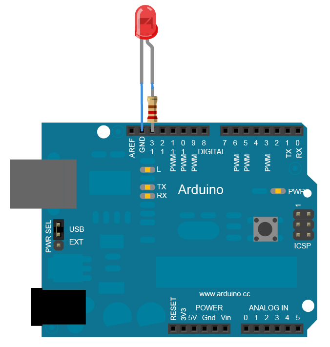
Figure 11: LED connected to the Arduino Board.
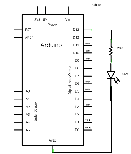
Figure 12: Schematic of LED connected to the Arduino board.
Dimmer Function: The hardware needed to dim the LED is same. But in this case, the 220 ohm current limiting resistor is connected to digital pin 9, with an LED in series. In this case, the software send the data in individual bytes, each of which ranges in value from 0 to 255, which controls the brightness of the LED. The corresponding circuit is shown in Figure 13 and Figure 14.
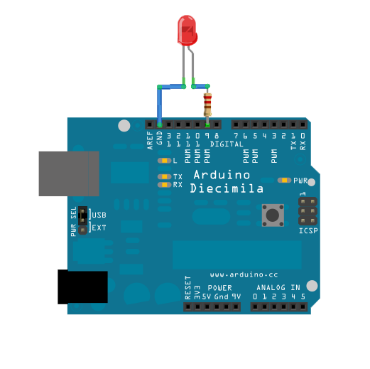
Figure 13: Circuit of LED Connected to the Arduino Board for dimmer function.
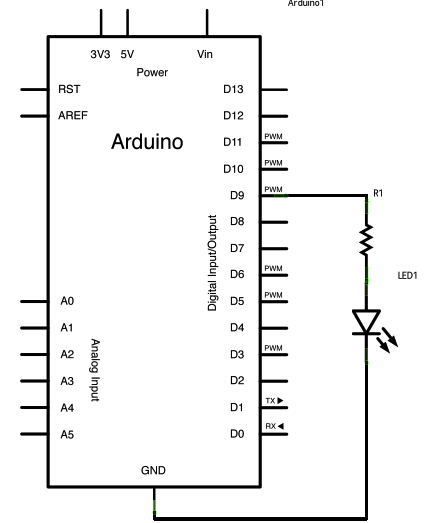
Figure 14: Schematic of LED connected to the Arduino Board for dimmer function.
Step 2: Connecting the LCD
Hardware Used
- Arduino Board
- LCD Screen (compatible with Hitachi HD44780 driver)
- 10k ohm potentiometer
- 220 ohm resistor
- Breadboard
Circuit
The circuit is shown in Figure 15 and Figure 16 below. To wire the LCD screen to board, the following pins are connected.
- LCD RS pin to digital pin 12
- LCD Enable pin to digital pin 11
- LCD D4 pin to digital pin 5
- LCD D5 pin to digital pin 4
- LCD D6 pin to digital pin 3
- LCD D7 pin to digital pin 2
Additionally, a 10k pot is wired to +5V and GND, with its output to LCD screens VO pin (pin3). A 220 ohm resistor is used to power the backlight of the display on pin 15 and 16 of the LCD connector.
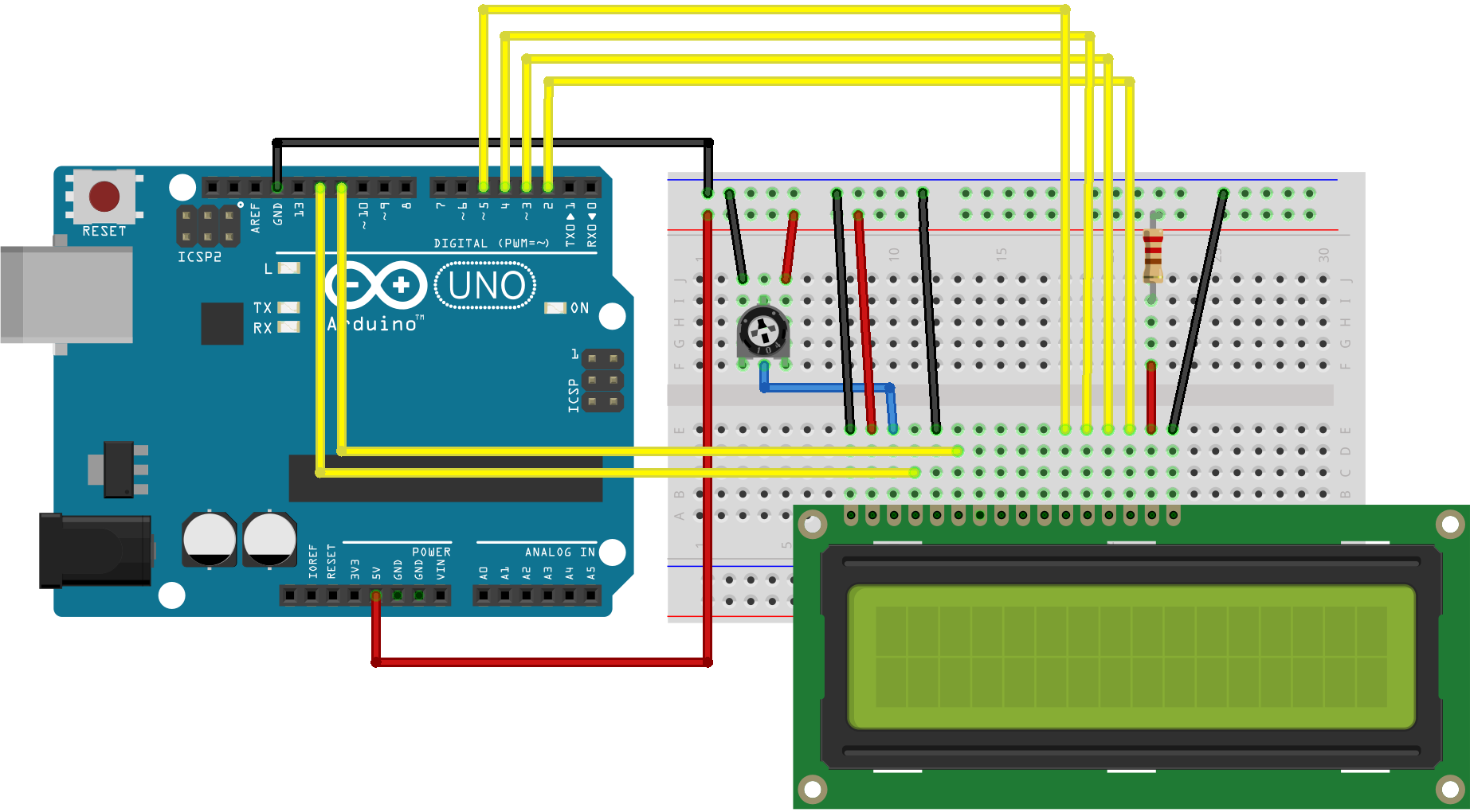
Figure 15: Circuit of LCD connected to the Arduino board.
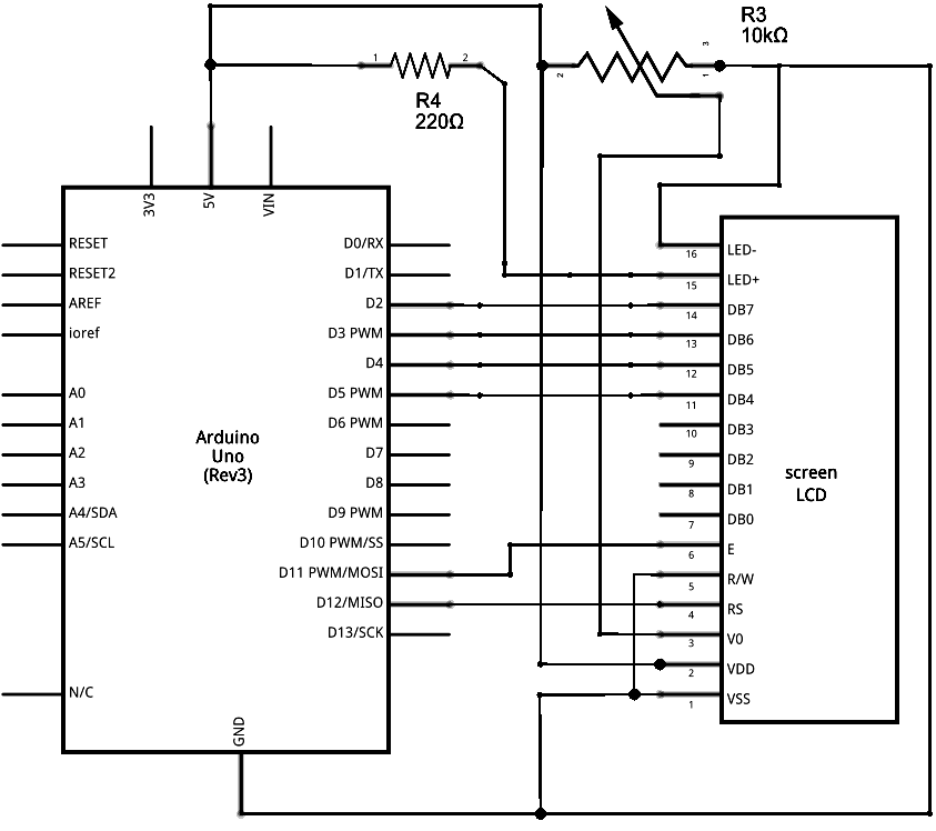
Figure 16: Schematic of LCD connected to the Arduino Board.
Step 3: Connecting the Servo Motor
In this project, it is chosen to swift the shaft of a RC servo motor back and forth across 180 degrees.
Hardware Used
- Arduino Board
- Servo Motor
- hook-up wire
Circuit
The circuit is shown in Figure 17 and Figure 18. Servo motors have three wires: power, ground, and signal. The power wire is typically red, and is connected to the 5V pin on the Arduino. The ground wire is typically black or brown and is connected to a ground pin on the board. The signal pin is typically yellow, orange or white and is connected to pin 9 on the board. When the LED is integrated for dimmer function then it was shifted to Pin 10.
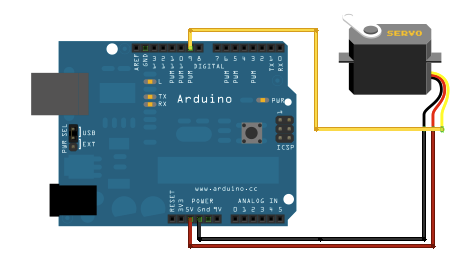
Figure 17: Servo motor connected to Arduino board.
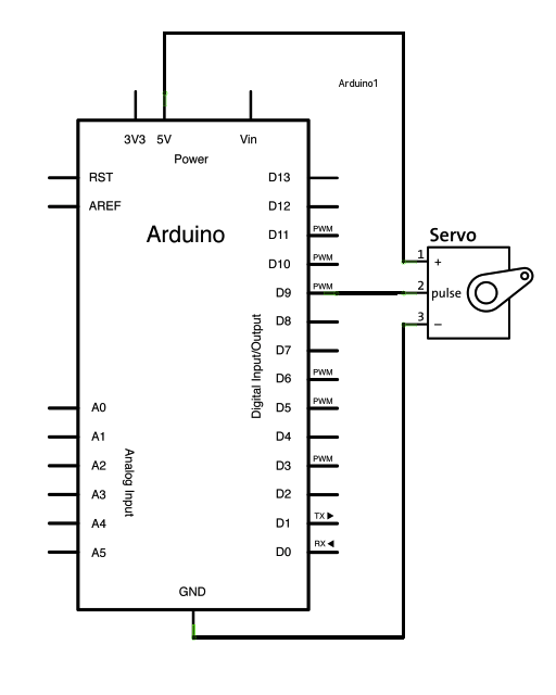
Figure 18: Circuit of connecting servo motor to Arduino board.
Step 4: Connecting the IR Remote
Hardware Used
- Arduino Board
- IR module
- IR remote
Circuit
The IR components and circuit are shown in Figure 19 and 20. IR receiver modules are used to receive IR signals. These modules work in 38 KHz frequency. When the sensor is not exposed to any light at its working frequency, the Vout output has a value equal to VS (power supply). With exposing to a 38 kHz infrared light, this output will be zero. The first step is to find the code for the Remote Control Buttons to be used. In this project, we are using 1 and 2 buttons. A connection was set up between the Arduino and an IR sender and receiver. Buttons 1 and 2 are pressed on the IR remote (sender), which sends a specific signal to the receiver and it is displayed on the Serial Monitor window. For this purpose, the IRRemote.h library was also installed. After finding the code for each button, these are used to control the commands as Button 1 for ON and Button 2 for OFF. The corresponding codes are given in Appendix at the end of the report.

Figure 19: IR receiver module and remote control.

Figure 20: IR receiver module connected to Arduino.
Light sensor
Hardware Used
- Arduino
- Resistance
- LDR
Circuit
LDR uses a pair of serial resistors to distribute the voltage supplied by the source between its terminals, as shown below in Figure 21:

Figure 21: Voltage divider of LDR sensor.
The Vout changes according to the following equation:
Vout=RLDR+R. Vin
As LDR sensor resistance decreases, the Vout increases. It is maximum when LDR resistance is null and minimum when LDR resistance is maximum (fully dark). In this project, R is fixed to a 1 kΩ. So, when LDR is fully lighted, i.e., LDR resistance value close to 0 Ω then the output will be 5V. When it is fully dark, then LDR resistance value will be very high in MΩ, then the output will be close to 0V. Now, the Arduino has a 10-bit ADC, the values of the pin where the LDR sensor is connected will be between 0 and 1024. So, with an output of 5 V, ADC value will be 1024 and with an output of 0 V ADC value will be 0. In the project, 100 is chosen as threshold value. It is because for the LDR used, the gray dark region corresponds to 100 in practice. The overall circuit is shown in Figure 22.

Figure 22: Voltage divider of LDR sensor connected to Arduino.
Overall, when all the components are connected to Arduino Boards to build Device 1 and Device 2, then the respective systems are shown in Figures 23 and 24. Both devices are tested several times and found working fine.


Figure 23: Device 1 & Device 2 implemented using Arduino.
6.0 Critical Evaluation
Through the report´s development it is clear that all the initial set forth objectives have been accomplished. During this development process, several challenges were faced (e.g. finding variables, connecting devices etc) which gives a good learning experience. It also include significant research to match expectations. This project report is reflection of the application of theoretical knowledge gained to a real world application. It helps expanding the knowledge in different areas to obtain a final project where three main electronic parts meet; electronic design (hardware), programming (software) and communication between devices. The designed system is tested for many parameters of light and very promising results are noticed each time. The distance between the two devices is also changed to investigate the effect of noise on the performance of overall system. The designed system is found very robust and promising. From the research done, it is found that this project area has numerous real applications and a promising future. This technology is in constant expansion and its scope is growing to cover more important areas like security, accessibility and user´s comfort. In future, more efforts will be focused to do its integration to mobile and cloud applications. As a summary, I have dealt with important parts of the degree I studied, using the knowledge acquired and increasing it, obtaining the know-how to get myself out in the professional market.
7.0 References
- https://create.arduino.cc/projecthub/electropeak/use-an-ir-remote-transmitter-and-receiver-with-arduino-1e6bc8 cited on 15th December 2019
- https://www.arduino.cc/en/tutorial/sweep cited on 18th December 2019
- https://www.arduino.cc/en/Tutorial/HelloWorld cited on 20th December 2019
- Lab Manual: Arduino Duemilanove Workbook 7CC03
- Antiquitas (Dec, 2019). Grecia III: Herón de Alejandría. Available in: http://historiautomatas.blogspot.com.es/2010/06/grecia-iii-heron-de-alejandria.html
- Atmel ATmega640/V-1280/V-1281/V-2560/V-2561/V (Dec, 2019) California: Atmel Corporation. http://www.atmel.com/Images/Atmel-2549-8-bit-AVR-MicrocontrollerATmega640-1280-1281-2560-2561_datasheet.pdf
- Historia del PLC, Modicon, Modbus. Unicrom (Dec, 2019). Available in: http://unicrom.com/historia-del-plc-modicon-modbus/ Anna Merino Herreros 63
Appendix
Appendix A.1 Code For Transmitter
/*
CODE for TX
Built Mr Omar
The Code does the following jobs:
There are two Arduino Boards with each having XBEE shields.
These are called ABX1 and ABX2. ABX stands here for Arduino Board XBEE
This code is for Transmitter part
It uses two types of sensors: Light/Photo Sensor and IR Sensor
1) Light Sensor: It Senses the light using photo sensor. If there is light then it sends H.
If there is no or low light then it sends L.
2) Remote Sensor: Same if the Remote Button 1 is pressed then it sends H
If the Remote Button 2 is pressed then it sends L
Special Dimmer Function: It also has a dimmmer LED function. This tells how much time (from ON to OFF) it takes between the operation of the sensors between H and L function.
Its brightness is changed, which indicates that it is reading and sending the signal from sensors.
*/
/*————————–
Main Library Files
*/
#include <IRremote.h> //including infrared remote header file
int RECV_PIN = 7; // the pin where you connect the output pin of IR sensor
IRrecv irrecv(RECV_PIN);
decode_results results;
int light = 0; // store the current light value
const int ledPin = 9; // the pin that the LED is attached to
// Setup code
void setup() {
Serial.begin(9600); // Define the Baud Rate
irrecv.enableIRIn(); // Enable IR
// initialize the ledPin as an output:
pinMode(ledPin, OUTPUT);
}
//————————
// Main code starts and run repeatedly:
void loop() {
light = analogRead(A0); // read and save value from Photo sensor
if (irrecv.decode(&results)==1) // Check if there is anything from IR Remote sensor
{
if (results.value == 16724175) // If Remote Button 1 is pressed
{
Serial.println(“H”); // Send H
for (int i = 256; i > 0; i=i-5)
{
analogWrite(ledPin, i); // i is brightness
delay(50);
}
}
else if (results.value == 16718055) // If Remote Button 1 is pressed
{
Serial.println(“L”); // Send L
}
irrecv.resume();
}
else if (light > 100) // Check if there is Light
{
Serial.println(“H”);
for (int i = 256; i > 0; i=i-5)
{
analogWrite(ledPin, i); // i is brightness
delay(50);
}
}
else if (light <= 100) // Check if there is less Light or Dark
{ // If it’s dark…
Serial.print(‘L’);
}
delay(1000); // Delay of 1 second
}
Appendix A.2: Code for Receiver
/*
CODE RX
Built Mr Omar
The Code does the following jobs:
There are two Arduino Boards with each having XBEE shields.
These are called ABX1 and ABX2. ABX stands here for Arduino Board XBEE
LCD: This Board receives H or L from the other board through XBEE
and Displays ON for H and OFF for L on the LCD Screen
The brightness of LCD can be adjusted through the potiometer
Motor: It also controls a motor in 180 degrees clockwise for ON and anticlockwise for OFF.
*/
// include the libraries
#include <LiquidCrystal.h>
#include <Servo.h>
// Define the variables
const int ledPin = 13; // the pin that the LED is attached to
int incomingByte; // a variable to read incoming serial data into
// initialize the LCD library with the numbers of the interface pins
LiquidCrystal lcd(12, 11, 5, 4, 3, 2);
// Initialise the Servo
Servo myservo; // create servo object to control a servo
// twelve servo objects can be created on most boards
int pos = 0; // variable to store the servo position
// Single loop
void setup() {
//——Set UP for LCD———-
// set up the LCD’s number of columns and rows:
lcd.begin(16, 2);
lcd.setCursor(0,0);
// Print a message to the LCD.
lcd.print(“Home Automation”);
lcd.setCursor(1,1);
lcd.print(“By OMAR”);
//——Set UP for XBEE———-
// initialize serial communication:
Serial.begin(9600);
// initialize the LED pin as an output:
pinMode(ledPin, OUTPUT);
myservo.attach(9); // attaches the servo on pin 9 to the servo object
pos=0;
}
void loop() {
// Do LCD Settings First
lcd.setCursor(0, 1);
// see if there’s incoming serial data from XBEE:
if (Serial.available() > 0) {
// read the oldest byte in the serial buffer:
incomingByte = Serial.read();
// if it’s a capital H, turn on the LED:
if (incomingByte == ‘H’) {
digitalWrite(ledPin, HIGH);
// print ON on LCD:
lcd.clear();
lcd.print(“ON”);
if (pos==0)
{
for (pos = 0; pos <= 180; pos += 1) { // goes from 0 degrees to 180 degrees
// in steps of 1 degree
myservo.write(pos); // tell servo to go to position in variable ‘pos’
delay(15); // waits 15ms for the servo to reach the position
}
pos=180;
}
}
// if it’s an L (ASCII 76) turn off the LED:
if (incomingByte == ‘L’) {
digitalWrite(ledPin, LOW);
lcd.clear();
lcd.print(“OFF”);
if (pos==180)
{
for (pos = 180; pos >= 0; pos -= 1) { // goes from 180 degrees to 0 degrees
myservo.write(pos); // tell servo to go to position in variable ‘pos’
delay(15); // waits 15ms for the servo to reach the position
}
pos=0;
}
}
}
}
Cite This Work
To export a reference to this article please select a referencing stye below:
Related Services
View all


DMCA / Removal Request
If you are the original writer of this essay and no longer wish to have your work published on UKEssays.com then please click the following link to email our support team:
Request essay removal